This section informs about the different object types of Ayam and about the property GUIs that appear in the properties section of the main window if a single object and a property have been selected.
Note that the "Help on object" and "Help on property"
main menu entries in Ayam can be used to directly jump to the appropriate
sub-section of this part of the documentation.
Documentation on the standard properties (Transformations, Attributes, Material, Shader, and Tags) can be found in section Standard Properties.
Furthermore, this section contains information about all tag types, see section Tags.
In the next sections general object capabilities will be briefly documented in tables like this:
| Type | Parent of | Material | Converts to / Provides | Point Edit |
| Object Type | No / Object Type+/∗ | Yes/No | N/A / Children / Object Type+/∗ | Yes/No* |
The capabilities are:
"crtOb" scripting interface command;Example:
| Type | Parent of | Material | Converts to / Provides | Point Edit |
| Revolve | NCurve / Trim+ | Yes | NPatch+ | No* |
Explanation:
"Revolve",
i.e. it can be created from scripts using the command "crtOb Revolve";This section provides an overview on the object types available in Ayam (since there are so many). The object types are grouped by application in the following sections.
These objects help to organize/structure the scene; view, camera, light, and material objects are also listed here (even though deserving an own section each):
| Type | Parent of | Material | Converts to / Provides | Point Edit |
| Root | View+ | No | N/A | No |
| Level | Any+ | Yes | N/A / Children+ | No |
| Clone | Any+ | No | Children+ | No* |
| Mirror | Any+ | No | Children+ | No* |
| Instance | No | No | Master | No* |
| Select | Any+ | No | N/A / Children+ | No |
| RiInc | Any | No | N/A | No |
| RiProc | No | No | N/A | No |
| View | NPatch | No | N/A | Yes |
| Camera | No | No | N/A | Yes |
| Light | No | No | N/A | Yes |
| Material | No | N/A | N/A | No |
These objects serve as geometric primitives in CSG hierarchies:
| Type | Parent of | Material | Converts to / Provides | Point Edit |
| Box | No | Yes | NPatch∗ | No* |
| Sphere | No | Yes | NPatch+ | No* |
| Disk | No | Yes | NPatch | No* |
| Cone | No | Yes | NPatch+ | No* |
| Cylinder | No | Yes | NPatch+ | No* |
| Torus | No | Yes | NPatch+ | No* |
| Paraboloid | No | Yes | NPatch+ | No* |
| Hyperboloid | No | Yes | NPatch+ | No* |
These objects are mainly used as child objects for the surface generating tool objects:
| Type | Parent of | Material | Converts to / Provides | Point Edit |
| NCurve | No | No | N/A | Yes |
| ICurve | No | No | NCurve | Yes |
| ACurve | No | No | NCurve | Yes |
| NCircle | No | No | NCurve | No* |
These objects enable direct manipulation of freeform surfaces:
| Type | Parent of | Material | Converts to / Provides | Point Edit |
| NPatch | NCurve+/ Level+ | Yes | PolyMesh | Yes |
| IPatch | No | Yes | NPatch | Yes |
| APatch | No | Yes | NPatch | Yes |
| BPatch | No | Yes | NPatch | Yes |
| PatchMesh | No | Yes | NPatch | Yes |
These objects modify existing curves or create new curves:
| Type | Parent of | Material | Converts to / Provides | Point Edit |
| ConcatNC | NCurve+ | No | NCurve | No* |
| ExtrNC | NPatch | No | NCurve | No* |
| OffsetNC | NCurve | No | NCurve | No* |
These objects create freeform surfaces from curves or other surfaces:
| Type | Parent of | Material | Converts to / Provides | Point Edit |
| Revolve | NCurve / Trim+ | Yes | NPatch+ | No* |
| Extrude | NCurve+ / Trim+ | Yes | NPatch+ | No* |
| Swing | NCurve∗ / Trim+ | Yes | NPatch+ | No* |
| Sweep | NCurve∗ / Trim+ | Yes | NPatch+ | No* |
| Birail1 | NCurve∗ / Trim+ | Yes | NPatch+ | No* |
| Birail2 | NCurve∗ / Trim+ | Yes | NPatch+ | No* |
| Skin | NCurve∗ / Trim+ | Yes | NPatch+ | No* |
| Gordon | NCurve∗/ Level / NPatch / Trim+ | Yes | NPatch+ | No* |
| Bevel | NCurve+ / Trim+ | Yes | NPatch | No* |
| Cap | NCurve+ / Trim+ | Yes | NPatch | No* |
| Text | No | Yes | NPatch+ | No* |
| Trim | NPatch / NCurve+/ Level+ | Yes | NPatch | No* |
| ConcatNP | NPatch∗/ NCurve∗ / Trim+ | Yes | NPatch+ | No* |
| ExtrNP | NPatch | Yes | NPatch+ | No* |
| OffsetNP | NPatch | Yes | NPatch+ | No* |
These objects complement the Ayam feature set and allow objects modelled in the polygonal or subdivision modelling paradigms to be included in Ayam scenes:
| Type | Parent of | Material | Converts to / Provides | Point Edit |
| PolyMesh | No | Yes | SDMesh | Yes |
| SDMesh | No | Yes | PolyMesh | Yes |
These objects create/modify arbitrary other objects from scripts or define entirely new object types via the custom object plugin mechanism.
| Type | Parent of | Material | Converts to / Provides | Point Edit |
| Script | Any+ | No | Any | No* |
| MetaObj | MetaComp+ | Yes | PolyMesh | No |
| MetaComp | No | No | N/A | No |
| SDNPatch | No | Yes | PolyMesh | Yes |
| SfCurve | No | No | NCurve | No* |
| SDCurve | No | No | NCurve | Yes |
| BCurve | No | No | NCurve | Yes |
A number of Script objects scripts are already distributed with Ayam:
| Type | Parent of | Material | Converts to / Provides | Point Edit |
| Helix | No | No | NCurve | No* |
| Spiral | No | No | NCurve | No* |
| TCone | No | No | Hyperboloid | No* |
| CBox | No | No | NPatch | No* |
| TCircle | No | No | NCurve | No* |
| Oval | No | No | NCurve | No* |
| DualSweep | NCurve* | No | NPatch | No* |
| TSurf | NCurve* | No | NPatch | No* |
| ExtrudeN | NCurve | No | NPatch | No* |
| Polyhedron | No | No | PolyMesh | No* |
These objects help to organize/structure the scene; view, camera, light, and material objects are also listed here (even though deserving an own section each).

There is always exactly one Root object in the scene. This object is something special in that it can not be deleted or copied. The Root object holds rendering options global to the scene like RiOptions, atmosphere and imager shaders. Furthermore, all currently open view windows are represented as child objects of the Root object.
If the Root object is hidden, the little red/green/blue coordinate system will not be drawn in any view.
The Root object also aids in per-scene window geometry management using SaveMainGeom and SavePaneLayout tags (see also sections SaveMainGeom and SavePaneLayout).
The following table briefly lists some capabilities of the Root object.
| Type | Parent of | Material | Converts to / Provides | Point Edit |
| Root | View+ | No | N/A | No |
The global scene rendering options are documented in the following sections.
This property carries RenderMan Interface options. Both, standard and BMRT specific options may be set using this property. For the sake of brevity only a short description of the available options will be given here. Please refer to the documentation of the RenderMan Interface and the documentation of BMRT for more detailed information about the options.
The RiOptions property consists of the following elements:
"Width", "Height", if greater than zero this value
will be used for the image size instead of the corresponding
dimension of the view window, but only for real RIB export operations,
not for the QuickRender and not for the Render actions in view windows.
QuickRender and Render actions will always use the dimensions of the
view window instead.
"StdDisplay", if this is enabled, a standard display
statement will be written to the RIB, which looks like this:
Display "unnamed.tif" "file" "rgba"
"Variance", maximum allowed variance of two pixel sample values.
The default 0.0 causes no setting in the RIB. If the variance is
"Samples_X", "Samples_Y" number of samples taken per
pixel. Only written to the RIB if "Variance" is 0.0.
"FilterFunc", function used to filter final pixel values.
"FilterWidth", "FilterHeight" size of the pixel filter.
"ExpGain", exposure gain, can be used to control the
overall brightness of the rendering.
"ExpGamma", exposure gamma, can be used to control the
midtone brightness of the rendering.
"RGBA_ONE", "RGBA_MIN", "RGBA_MAX",
"RGBA_Dither", specify quantisation and dithering; these settings
adjust the output bit depth and value range;
setting all four entries to 0 disables the quantization and the
output will be floating point values;
"MinSamples", "MaxSamples", minimum and maximum number
of samples per pixel (for variance based sampling).
"MaxRayLevel", maximum number of recursive rays.
"ShadowBias", minimum distance that one object has to
be in order to shadow another object.
"PRManSpec", toggles behaviour of BMRT's specular() function
between PRMan compatible (default) and RI standard compatible.
"RadSteps", number of radiosity steps, the default 0 leads
to no radiosity calculations to be performed.
"PatchSamples", minimum number of samples per patch to
calculate the radiosity form factors for this patch.
"Textures", "Shaders", "Archives" and "Procedurals"
are search paths for the renderer.
"TextureMem" and "GeomMem" determine how much
memory rendrib (from BMRT) should use at maximum to cache textures and
tesselated geometry.Renderer specific options may also be set with RiOption tags
(see section
RiOption Tag), most comfortably
added via the main menu "Special/Tags/Add RiOption"
(see section
Tags Special Menu).
The Imager and Atmosphere properties let you define shaders for the Root object, please refer to section Shader Properties for information on how to deal with shader property GUIs.
Imager shaders are executed once for every rendered pixel, they may e.g. be used to set a specific background color or backdrop image.
Atmosphere shaders are volume shaders that may be used to implement global atmospheric optical effects like fog.
The Root object appears in RIB output in different places as collection of RenderMan Interface options and imager as well as atmosphere shaders.
The exact RIB statements used depend on the configuration of the
object and the preference setting "RIB-Export/RIStandard".
The Root object is the only object to support RiOptions, RiHider, and RiDisplay tags (see also section Tags).
Every view window (see also section Anatomy of a View) has a corresponding view object as a child object of the Root object. Using the properties of the view object, camera settings, the type of the view, and other things related to the view can be changed. Note that deleting the object that represents a view, will not close the view window. You will just lose a way to configure it. Please, do not mess with the objects in other ways (e.g. copy them), you are asking for trouble otherwise!
Each view is associated with a virtual camera.
The type of the view determines the default up-vector of that camera.
If the type is "Top" the up-vector corresponds to the world
Z-axis, else the world Y-axis.
The type of the view, additionally, determines the so called
input plane of the view. Interactive modelling actions in a view are
limited to that input plane (unless the view is switched to local modelling;
see also section
Editing in Local Spaces).[∗]
The standard input planes are as following: Front – XY-plane, Side – ZY-plane, Top – XZ-plane, Trim – XY-plane.
In perspective views no interactive modelling actions are possible, but the camera may be modified, objects can be picked, and points selected.
Views of type "Trim" are used to edit trim curves of NPatch objects
only. They display those trim curves as normal NURBS curves when the
current level is inside a NPatch.
The extensions of the patch in parameter-space are also drawn as a
dashed rectangle.
The trim curves should completely lie inside this rectangle.
Note that picking of objects currently does not work in views of type
"Trim".
The following table briefly lists some capabilities of the View object.
| Type | Parent of | Material | Converts to / Provides | Point Edit |
| View | NPatch | No | N/A | Yes |
The next sections detail the properties of the view object.
This section describes all elements of the "Camera" property:
"From" is the point where the camera (that is attached
to the view) is situated."To" is the point the camera is looking to."Up" is the up-vector of the camera."Near" defines the near clipping plane. A value of 0.0
means a default value (that depends on the type of the view) should
be used. Otherwise, near should always be positive for perspective views,
and smaller than far."Far" defines the far clipping plane. A value of 0.0
means a default value (that depends on the type of the view) should
be used. Otherwise, far should always be bigger than near."Roll" defines an angle by which the camera is rotated
around the axis that is defined by the points from and to."Zoom" is a zoom factor.Note that the up-vector is not checked for erroneous values
(e.g. pointing in the direction of from-to) when applying the changes
of the "Camera" property.
This section describes the elements of the "ViewAttrib" property:
"Type" specifies the type of the view. Front, Side, Top (all
parallel), Perspective and Trim (again parallel) may be selected."Width" and "Height" control the size of the view
window. It is currently not possible to resize internal views
with these elements."Redraw" toggles automatic redrawing of the view.
If this is disabled, no drawing takes place in the view until an
explicit redraw is requested (using the view menu, or the shortcut
<Ctrl+d>)."DrawingMode" allows to specify the drawing mode of
the view: "Draw" draws a wire-frame, "Shade" draws lighted
surfaces. Note that the lighting is in no way an exact (or even similar)
representation of the light information as specified with Light objects
in the scene.
Instead, a single light source, located at the camera origin
(a headlight), will be used.
"ShadeAndDraw" combines surfaces and wire-frames.
"HiddenWire" shows hidden wire-frames and silhouettes.
See also section
Drawing Modes.
"DrawSel" toggles drawing of selected objects. If this is
enabled, only the current selected objects will be drawn."DrawLevel" toggles drawing of the objects of the current
level only. If this is enabled, only the objects of the current
level will be drawn."Grid" is the grid size, 0.0 means no grid."DrawGrid" toggles drawing of the current grid."UseGrid" toggles, whether the current grid should be
used by the interactive modelling actions.
See also section
Modelling Actions.
"ModellingMode" enables editing in local object spaces.
See also section
Editing in Local Spaces.
"DrawBG" controls whether the background image (specified
by the "BGImage" option below) should be drawn. If a NPatch object
is present as child of the View object,
the image will be mapped onto this object instead of filling the
complete view window background.
"BGImage" is the name of a TIFF image file, that will
be used as texture for the background image. Ayam will read this image file
when the changes to the "ViewAttrib" property are applied,
but also reread the image file if the notification callback of the view
object is invoked (e.g. using the main menu entry
"Tools/Force Notification").
"Mark" is the marked point (in world coordinates) for
the rotate and scale about modelling actions.
"SetMark" controls whether the data from the "Mark"
entries above should be used as new mark coordinates when the
changes to the "ViewAttrib" property are applied.
"EnableUndo" allows to control undo for the interactive
view actions, e.g. panning or zooming a view.
If this option is disabled, these actions will not be recorded in the
undo system and also do not change the scene changed state.View objects act in special ways, when certain objects are dropped onto them in the tree view:
When a Camera object is dropped onto a View object, the camera settings of the Camera object will be copied to the views camera.
When a Light object of type "Spot" is dropped onto a View object,
the views camera will be changed,
so that the user looks along the light to see what objects of the scene
are lit by the light object (this works best with perspective views
that have equal width and height).
It is also possible, to directly drag arbitrary objects from the tree view to a view window: for geometric objects, the view then performs a zoom to object operation, for cameras and light sources the views camera will be changed as if the object was dropped onto a View object in the tree view (see the above description).[∗]
Camera objects are used to temporarily save camera settings of views. Therefore, they has just have two properties explained above, see sections Camera and Attributes Property.
The following table briefly lists some capabilities of the Camera object.
| Type | Parent of | Material | Converts to / Provides | Point Edit |
| Camera | No | No | N/A | Yes |
When a View object is dropped onto a Camera object the camera settings from the view will be copied to the Camera object.
Camera objects never appear in RIB output.
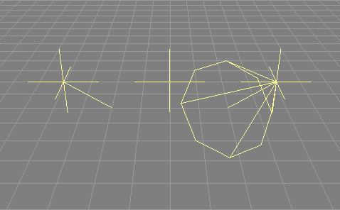
Light objects represent light sources.
There are currently four different light types available in Ayam:
"Point", "Distant", "Spot", and "Custom"
(see also the image above).
Point-, Distant-, and Spotlights:
These standard light sources have well defined parameters that
will be displayed in the "LightAttr" property.
Please refer to the RenderMan documentation for more information
about these standard light sources (see section
References).
Light sources of type "Custom" use the attached light shader.
Note that Ayam is trying to guess from the names of the light shader
arguments to draw the light.
The names "from" and "to" denote location and destination
of the light source. Those names should not be used for other things
in the light shaders.
In contrast to the light sources as defined in the RenderMan
interface, Ayam light sources are always global by default. This
means, regardless of the place of a light source in the scene
hierarchy, it will always light all other objects (unless the
"IsLocal" attribute is used).
Note that the effect of a light source can not be previewed in shaded Ayam views, currently. However it is possible to estimate the effect of a spot light source by simply dropping it into a perspective view window; the view will then adapt the camera attributes (from, to, and zoom) of the view to show the objects lit by the spot.
The following table briefly lists some capabilities of the Light object.
| Type | Parent of | Material | Converts to / Provides | Point Edit |
| Light | Yes | No | N/A | Yes |
The parameter "Type" determines the type of the light source.
Depending on the type of the light source, the light attribute
property contains different sets of parameters. Parameters that
are not displayed will not be used on RIB export, consequently.
When the type of a light source is changed, the property GUI will
be adapted to show only the options available for the new light
source type. Note that this adaptation happens when the "Apply"-button
is used.
"IsOn" allows you to switch the light off or on. The default
value is on.
"IsLocal" controls whether the light source should light
just local objects (objects, that are defined in the same level
in the scene hierarchy as the light source object or below it) or
all objects in the scene.
The default is off, all objects in the scene are lit.
The "IsLocal" attribute is ignored for lights that are
defined in the root level of the scene. Mind also that shadow maps
will always contain shadows from all objects in the scene,
regardless of the "IsLocal" attribute of the light source.
Using the light attribute "Shadows" you may determine
whether the light source should cast shadows.
The default is off, no shadows. Note that this option will not
magically enable shadows on renderers that create shadows by
shadow maps. It will merely be interpreted by raytracing
renderers like BMRT.
The parameter "Samples" determines the number of times to sample
an area light source, independent of pixel samples, the default value
is 1. This attribute is available for custom lights only.
"UseSM" determines, whether shadow maps should be created
and used for this light source. The resolution of the
shadow map may be determined by the attribute "SMRes". If
"SMRes" is 0, a default of 256 by 256 pixels will be used.
These options are for renderers that do not support raytraced
shadows like e.g. Aqsis only.
For lights of type "Distant" the "Scale" attributes
of the "Transformations" property of the light
object may be used to scale the camera transformation
used for the creation of the corresponding shadow map.
Values of 1 for "Scale_X" and "Scale_Y" create
a shadow map that is sized 1 by 1 units in world space.
All other parameters that may appear in the "LightAttr"
property are the standard parameters for the standard RenderMan
light sources: distant, point, and spot:
"From" and "To" denote position and target of the light
source as point in space. You may edit both points using standard
point editing actions (see also section
Modelling Actions)."Color" is the color of the light emitted by the light source."Intensity" is the intensity of the light emitted by the
light source. Note that the standard point and spot lights have
a quadratic falloff (with distance), that requires the intensity
to be set to quite high values in order to achieve some
illumination effect (e.g. around 30 for the standard distance of
"From" and "To" of a spot light)."ConeAngle" is the angle of the beam of a spot light."ConeDAngle" (cone delta angle) is the angle that determines a
falloff area at the edge of the beam of a spot light."BeamDistrib" (beam distribution) determines, how the light
falls off in the beam of the spot light. Larger values result in narrower
lit areas.In order to ease the parameterisation of spot lights, the light source object may be dropped onto a view object or into a view window (preferably one with a perspective viewing transformation and with equal width and height) to see what objects of the scene are actually lit by the light object.
Using shadow maps requires the global preference setting
"RIB-Export/ShadowMaps" to be switched to "Automatic"
or "Manual" (both settings will be explained below).
Furthermore, for each light source for which a shadow map should be
created, the attributes "IsOn" and "UseSM" have to be
switched on.
Automatic Creation of ShadowMaps
If the preference setting "RIB-Export/ShadowMaps" is set to
"Automatic",
Ayam will create a special version of the RIB on export, that creates
all shadow maps automatically upon rendering. This is done by rendering
depth images from the position of every light source that casts shadows.
Special light source shaders later pick up these depth images
and calculate shadows.
This approach implies, that the scene is rendered multiple times.
To reduce the size of the RIB, the objects to be rendered
are written to a second RIB file named "<ribfilename>.obj.rib".
This file is read from the main RIB several times via
"ReadArchive". The RIB contains multiple frames which may
also be rendered separately if the frame number is known.
To help picking the right frame number for the image
(e.g. to re-render just the final image, when only a material setting was
changed, and no shadow casting lights were moved and no shadow casting
geometry was changed),
a comment with the frame number of the last frame (the image) will be
written as last statement to the RIB.
Because multiple files (RIBs and shadow maps) are used, it is suggested
to change the preference setting "RIB-Export/RIBFile" to
"Scenefile". This will strip the leading absolute path component
from the filenames so that the exported scene may be moved from one
system to another more easily.
Do not render directly from a view window to the display when the
"ShadowMaps" "RIB-Export" preference option is set to
"Automatic".
The renderer may not write image files when the command line option
to render directly to the display (-d for rendrib, or -fb for Aqsis) is
in use. Consequently, this may also inhibit writing of the shadow maps,
so that the resulting image will look wrong, or the renderer will only
render the shadow map to the display and then simply stop.
Manual Creation of ShadowMaps
If the preference setting "RIB-Export/ShadowMaps" is set to
"Manual",
the exported scene will not create the shadow maps upon rendering but rather
expects them to be present already. They can be created manually
using the view menu entries
"View/Create ShadowMap",
"View/Create All ShadowMaps"
or the main menu entries
"Special/RIB-Export/Create ShadowMap",
"Special/RIB-Export/Create All ShadowMaps".
Rendering the scene multiple times will be faster because the shadow maps
will not be re-created each time. However, the user is responsible to update
the shadow maps after certain scene changes, like for instance changes
to the shadow casting geometry or light sources.
ShadowMap Types
Ayam supports three different methods for the creation of shadow maps for certain types of light sources: point, distant, and spot:
The point method is used with
lights of type "Point" and custom lights that have a light
shader argument named "from".
Six shadow maps pointing in all possible axis aligned
directions and named "<rib>.point<num>_<dir>.shd"
(where "<rib>" is the name of the RIB,
"<num>" is the number of the light source that makes
use of shadow maps and "<dir>" is one of
"x+", "x-", "y+", "y-", "z+", or "z-")
will be created.
The distant method is used with lights of type "Distant"
and custom lights that have a light
shader argument named "from" and a light
shader argument named "to".
One shadow map is created and named
"<rib>.dist<num>.shd".
By default, the size of the shadow map is 1 by 1 units in world space,
but this may be adapted using the scale transformation attributes of
the light object.
The spot method is used with lights of type "Spot"
and custom lights that have a light
shader argument named "from", a light
shader argument named "to", and a light shader argument named "coneangle".
One shadow map is created and named
"<rib>.spot<num>.shd".
The spot method uses the cone angle (and additionally the delta cone
angle, if present) argument to determine the size of the shadow map
in world space.
If a light object of type "Spot", "Distant" or
"Point" is used, Ayam automatically changes the name of the
exported light shader to "shadowspot", "shadowdistant",
and "shadowpoint" respectively. Additionally, the shader
will be parameterised to use the created shadow maps.
If the light source is of type "Custom", no automatic renaming
and adjusting of the shader takes place. This means, you have
to make sure that the shader really uses the shadow maps, by
selecting the right shader and parameterising it accordingly.
See the discussion above for the names of the shadow map files.
Those file names, most probably, will have to be entered as parameter
to the light shader.
For example, you will not get any shadows if you use a light source of
type "Custom" with the normal "distantlight" shader attached,
even though Ayam is able to create the necessary shadow maps. The
normal "distantlight" shader just makes no use of the shadow maps.
You have to manually switch to a shader that
makes use of the shadow maps ("shadowdistant" in this case) to
actually get shadows.
ShadowMap Mini Tutorial
Here is a short example for a scene using a shadow map:
"RIB-Export") and set
"ShadowMaps" to "Automatic"."Transformations" property of the second box."LightAttr" property."Spot". Press "Apply"."IsOn": Yes,
"Intensity": 18.0,
"UseSM": Yes, "ConeAngle": 45.0, "BeamDistrib": 3.0,
"From": -2, 2, 2, "To": 1, 0, -1;
leave all other parameters at their default values."Type/Perspective")."View/Export RIB").This scene is distributed with Ayam as an example scene named
"shadowmaps.ay", see also the following image from that scene
that was created with an additional point light and Aqsis as renderer:
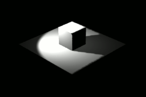
Note that for Aqsis you should add a RiHider hidden,depthfilter,s,midpoint tag to your Root object if shadow maps are in use. Other renderers might require additional tweaking using shadow bias RiOption tags. Please consult the documentation of your renderer on how to achieve the best results using shadow maps.
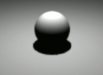
The common idealized standard light sources "Point", "Distant"
and "Spot" have no own geometric extension in space.
This means, shadows resulting from such light sources will have sharp
borders which does not look too natural.
Good looking soft shadows may be generated using area lights.
See also the image below.
Area lights may be created by simply placing a single object as child
object of a "Custom" light object that has the "arealight"
shader attached, i.e. the scene hierarchy looks like this:
+-AreaLight(Light)
  \-AreaLightGeometry(Sphere)
An example:
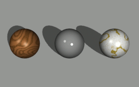
"arealight" light shader to it.There is an example scene named "arealight.ay" distributed with
Ayam, see also the following images from that scene that
were created with BMRT 2.6 as renderer:
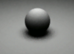
Material objects are used to attach RenderMan attributes and shaders to geometric objects. See also the image above that was rendered with BMRT 2.6 and uses materials with the following shaders, which are distributed with the renderer: wood2, ceramic, veinedmarble.
As long as geometric objects are connected to a material object, this material object may not be deleted.
The following table briefly lists some capabilities of the Material object.
| Type | Parent of | Material | Converts to / Provides | Point Edit |
| Material | No | N/A | N/A | No |
Using this property standard and BMRT specific RenderMan attributes may be set. Please refer to the documentation of the RenderMan interface and the documentation of BMRT for more detailed information about the RenderMan specific attributes.
"Color", the color of the object. If one of the entries is set
to a negative value (e.g. -1), the color will not be set at all
for this object, i.e. no RiColor call will be emitted upon export."Opacity", the opacity of the object, the default
(255 255 255) means the object is totally opaque. If one of the entries is
set to a negative value (e.g. -1), the opacity will not be set at all
for this object, i.e. no RiOpacity call will be emitted upon export."ShadingRate", determines how often shaders are evaluated for
a sample."Interpolation", determines how return values computed
by the shaders are interpolated across a geometric primitive."Sides", determines how many sides of the surface of a
geometric primitive should be shaded."BoundCoord", sets the coordinate system in which the
displacement bound is expressed."BoundVal", displacement bound value."TrueDisp", toggles true displacements on or off. Default off."CastShadows", determines how the object casts shadows:
the default "Os" means the object casts shadows according to it's
opacity; "None" object does not cast any shadows; "Opaque"
the object is completely opaque and casts shadows; "Shade"
the object has a complex opacity pattern determined by it's surface
shader, that is used in shadow calculations."Camera", "Reflection", and "Shadow" toggle
visibility attributes.These properties let you define shaders for the material object, please refer to section Shader Properties for information on how to deal with shader property GUIs.
Surface shaders may be used to procedurally encode lighting models and textures. Displacement shaders may procedurally deform the object while rendering. Interior and Exterior shaders are so called volume shaders that may be used to capture special optical effects, encoding how light is affected while passing through an object.
The MaterialAttr property contains attributes related to the management of material objects:
"Materialname" denotes the name of the material. Note
that material names have to be unique in a scene. If two
materials with the same name exist, only the first material
created with this name is "registered" and thus may be connected
to geometric objects."Refcount" shows how many geometric objects are connected to
(are of) this material. Note that connected or referring geometric objects
not necessarily have to live in the scene, they may as well temporarily
reside in the object clipboard."Registered" displays whether this material may be
connected to geometric objects, see the discussion about material names above.When geometric objects are dropped onto a material object they will be connected to this material object.
Material objects only appear in RIB output if connected to a geometric object (e.g. a Box).
The exact RIB statements used depend on the configuration of the
material and the preference setting "RIB-Export/RIStandard".
If all elements of the MaterialAttr property are left on their default values, only color and opacity will be written to the RIB:
RiColor(...);

RiOpacity(...);
RiDeclare("Ka", "float");

...

RiSurface("Ka", 0.9, ...);

...
No attempt is being made to re-order or sort objects in a level according to their attached materials, they will rather be exported in the order of their appearance in the level and thus each object with a material will also be prepended by a full material specification as described above.
Here is a complete example of a material description with the wood2 surface shader applied to a sphere:
...
Color 0.862745 0.862745 0.862745
Opacity 1 1 1
Declare "Ka" "float"
Declare "Kd" "float"
Declare "Ks" "float"
Declare "roughness" "float"
Declare "ringscale" "float"
Declare "txtscale" "float"
Declare "lightwood" "color"
Declare "darkwood" "color"
Declare "grainy" "float"
Surface "wood2" "Ka" [1] "Kd" [0.75] "Ks" [0.4] "roughness" [0.1]
"ringscale" [15] "txtscale" [1] "lightwood" [0.686275 0.439216 0.247059]
"darkwood" [0.34902 0.219608 0.0784314] "grainy" [1]
Sphere 1 -1 1 360
...
Level objects may be used to build object hierarchies and perform CSG operations.
Ayam does not offer a layer concept, but by grouping objects using levels and the hide/show tools, layer functionality may be emulated to a certain extent.
Organizing the scene and working in levels also increases the speed of object tree updates, as only the current level and its sub-levels are subject to a tree update if something in the object hierarchy changes.
Note that child objects of a level inherit the levels transformations,
material, attributes, and shaders. Inheritance of e.g. transformations
means:
If you have a NURBS patch in a level that is translated to (10,0,0),
the origin of the local coordinate system of the NURBS patch
will be situated at (10,0,0). If you decide to move the patch by a
value of 5 in X direction by setting a corresponding value in the
Transformations property of the patch object, the local coordinate
system of the patch will be placed at (15,0,0) in world coordinates,
i.e. a control point with the coordinate values (1,0,0) will be at (16,0,0)
in terms of world coordinates.
Note also that since Ayam 1.12, Level objects provide their child objects to their parent objects as a list. This means the following hierarchy is now valid:
+-Skin
  +-Level
    |-NCurve
    |-NCurve
    |-ICurve
    \-NCurve
The following table briefly lists some capabilities of the Level object.
| Type | Parent of | Material | Converts to / Provides | Point Edit |
| Level | Any+ | Yes | N/A / Children+ | No |
Levels do not have many object type specific properties, you may just
modify the type of the level using the attribute "Type".
Levels of type "Level" just group objects and inherit attributes.
Levels of type "Union", "Intersection", and "Difference"
are used to build CSG hierarchies. Additionally, they inherit attributes.
Note that Ayam is currently not able to correctly display the results
of CSG operations, all objects are always drawn completely, even though
a CSG operation would cut parts away.
However, since Ayam 1.8 there is a plugin available that is able to preview the results of CSG operations, see also section CSG preview using the AyCSG plugin.
The object hierarchy to cut away a part of a box using a sphere looks like this:
+-Level_of_Type_Difference(Level)
  |-Box
  \-Sphere
+-Level_of_Type_Difference(Level)
  |-Box
  |-Sphere
  \-Sphere
New solid primitives may be created with levels of type "Primitive".
+-Level_of_Type_Difference(Level)
  +-Level_of_Type_Primitive(Level)
  | |-Sphere_blue
  | \-Disk_red
  \-Box_grey
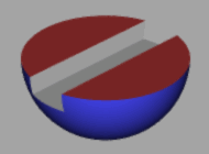
"ThetaMax" 180.0 (a hemisphere)
is manually capped by a disk object. The two objects need to be placed
into a level of type "Primitive" because each object alone is an
open surface and therefore not a valid CSG primitive. Both objects that
form the new primitive use a different material. In addition, a grey box
cuts away a part from the multi colored hemisphere.
The above CSG hierarchy is available as example scene file
"multicolcsg.ay".
See also this image:
Note that Ayam is not able to check, whether your new primitive obeys
the rule of total closeness. For instance, if the disk in the above
example would not totally cap the sphere (this happens if the disk
"ThetaMax" is not 360.0 or if it is not placed exactly at the
sphere) Ayam would not complain upon RIB export.
The rendered image would expose serious errors, however.
Furthermore, it is not necessary to enclose normal child objects
(e.g. quadrics with the "Closed" attribute set to on) of
CSG levels in primitive levels for RIB export. This is done by Ayam
automatically where needed.
The exact representation of a Level in RIB output depends on its type.
Normal Level objects appear in RIB output as Transformation hierarchies:
RiTransformBegin();

RiTranslate(...);

RiRotate(...);

RiScale(...);


«Children RIB output»


RiTransformEnd();
Level objects of type Union, Difference, or Intersection will additionally emit a call to SolidBegin, and each child will be properly declared as primitive, e.g.:
RiTransformBegin();

«Level Transformations»

RiSolidBegin(RI_DIFFERENCE);


RiSolidBegin(RI_PRIMITIVE);

«Child #1 RIB output»

RiSolidEnd();


RiSolidBegin(RI_PRIMITIVE);

«Child #2 RIB output»

RiSolidEnd();


RiSolidEnd();

RiTransformEnd();
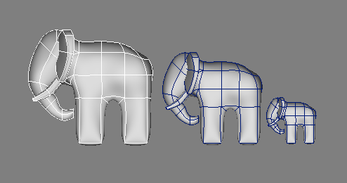
The term instance is unfortunately misleading (and can be very confusing if you are accustomed to the terminology of object oriented programming), but it is the term that seems to be used and understood by most computer graphic artists for this mechanism. A better term would be link, as an instance object has the same basic properties as a link in a Unix file system. A link is just a pointer to an original file, the same goes for an instance object: it is just a pointer to an original object (here also called master object). A link can be placed anywhere on the file system, an instance object can be placed anywhere in the scene hierarchy, and additionally, it can be transformed.
While the original purpose of instances is to save memory, in the tool object context instances also serve as a means to transport geometric data across the scene hierarchy to make tool objects depend on each other (see also section The Modelling Concept Tool-Objects). Note that in the tool object context, instance objects are the only objects, that are subject to a second round of provision.
Some simple rules for instancing:
If deleting of an object fails, and the error message
complains about the reference counter not being zero, then
the last rule was about to be violated. Clean the clipboard using
the menu "Special/Clipboard/Paste (Move)" and delete
or resolve all references first.
Ayam can also create instances for complete scenes automatically (see section Automatic Instancing).
To easily find the master object of an instance, just select the
instance, then use the main menu entry: "Edit/Master".
The following table briefly lists some capabilities of the Instance object.
| Type | Parent of | Material | Converts to / Provides | Point Edit |
| Instance | No | No | Master | No* |
Instance objects support the "RP" tag type
in a special way:
if the "Transformations" property is removed using a
"RP" tag, the instance does not provide objects with
an own set of transformation attributes (to ease hierarchy building
with e.g. "ExtrNC"/"ExtrNP" objects, where only
pointers to already existing objects are required and where it is
expected, that the instance reflects the master exactly, including
its transformation attributes).[∗]
The extract curve/surface tools automatically add such a tag to the instances they create.
To create such a tag manually, select the Instance object and enter into the Ayam console:
» addTag RP Transformations
This special case of an instance is sometimes also called reference.
This section contains additional information on instances and what happens to them when they are copied and pasted using the object clipboard.
All copies of instance objects, that are created by the object clipboard, always point to the same original master object. Therefore, it is not possible to copy a master object and some instances of it, so that the new instances point to the newly created master.
For example, when the following two objects are copied and pasted back to the scene
|-NCurve   <-----.
|                |
|-Instance  -----'
the following scene hierarchy results:
|-NCurve   <-----+-.
|                | |
|-Instance  -----' |
|                  | !
|-NCurve           |
|                  |
|-Instance  -------'
Nevertheless, it is possible to move complete sets of masters and their
instances through the scene hierarchy using drag and drop in the tree view or
using the object clipboard with
"Edit/Cut" and then "Special/Clipboard/Paste (Move)".
An Instance object may be converted to an ordinary object using the
main menu entry "Tools/Convert".
This process is also called resolving the instance.
To resolve all instance objects in a scene
to normal objects, also the main menu entry:
"Special/Instances/Resolve all Instances" can be used.
The RIB export of instances does not use the RiInstance facility of the RenderMan interface, but rather the more flexible ReadArchive mechanism.
This means, every master object in the scene will be written in a separate archive (RIB file) on disk, and every instance will cause that archive file to be read when rendering the RIB file. The resulting RIB file is not self contained: multiple files need to be transferred to other systems when rendering shall occur there.
This behaviour can be changed using the RIB export preference setting
"ResInstances": If this option is enabled, all instances
will be resolved temporarily to normal objects before being exported
to RIB. The resulting RIB file will then be self contained but probably
also much larger.
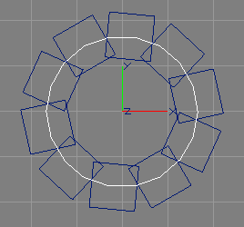
The Clone object allows to easily create and control an arbitrary number of instances of a single object, hereafter called the cloned object. The instances can be transformed (each by a certain amount expressed as difference between two instances) or placed on a trajectory curve (see also the image above).
If a second object is present as child of the Clone object it is treated as trajectory (or path) curve automatically. The process of placing the clones on the trajectory is very similar to the sweeping operation (see also section Sweep Object).
Thus, the default object hierarchy of a Clone object looks like this:
+-Clone
  |-Cloned-Object
  \-[Trajectory(NCurve)]
"NoExport" tag to it.
Otherwise the original object will appear twice, on the trajectory and
on its normal, untransformed, position. Note that the transformation
attributes of the cloned object will be completely overwritten when
placing the clones on the trajectory curve. If the cloned object has
distinct scale or rotation attributes it should be put inside a level
object like this:
+-Clone
  +-Level
  | \-Cloned-Object with non-standard Scale/Rotation
  \-Trajectory(NCurve)
It is not possible to create clones from objects that may not be master objects of instance objects, e.g. it is not possible to clone light objects or material objects. However, (since Ayam 1.7) it is possible to use instances as parameter objects.
If an instance object is used as cloned object on a trajectory
it can be placed in a level and the "NoExport" tag can
be added to the level object (as adding tags to Instance objects is
more involved), see the following hierarchy for an example:
+-Clone
  +-Level with NoExport tag
  | \-Instance
  \-Trajectory(NCurve)
Since Ayam 1.20 the mirror facility of the Clone object is realized through the new Mirror object (see also section Mirror Object). The mirror facility was integrated into the Clone object before.
The following table briefly lists some capabilities of the Clone object.
| Type | Parent of | Material | Converts to / Provides | Point Edit |
| Clone | Any+ | No | Children+ | No* |
The following attributes control the cloning process:
"NumClones" is the number of clones to create."Rotate" is only used, if a trajectory curve is present.
If it is enabled all clones will be aligned according to the normal of
the trajectory curve. Otherwise the rotation attributes will not be
touched when placing the clone on the trajectory.
"Translate_X", "Translate_Y", "Translate_Z",
"Rotate_X", "Rotate_Y", "Rotate_Z",
"Scale_X", "Scale_Y", "Scale_Z",
those attributes control the transformation of the instances created by
the Clone object. These attributes specify difference values
between two instances: the clone "n+1" is offset by "Translate_X",
"Translate_Y", and "Translate_Z" from the previous clone "n".
It is also rotated by "Rotate_X", "Rotate_Y", and "Rotate_Z"
and scaled by "Scale_X", "Scale_Y", "Scale_Z" in relation
to the previous clone.
Note however, that the transformation attributes do not affect the first clone.
The transformation attributes are also in effect if a trajectory curve is present, they will be applied after moving of the instance to the trajectory and rotating it.[∗]
| Mode | Use Child Transform | Use CloneAttrib Transform | Use Clone Transform |
| Clone | No | Yes | Yes |
| Trajectory | Yes | Yes | Yes |
| Mirror | Yes | N/A | Yes |
The Clone object may be converted to ordinary objects using the
main menu entry "Tools/Convert".
Upon conversion a Level object will be created, that contains the original object and the clones.
Clone objects appear in RIB output as a number of real objects, each with different transformation attributes.
As the original objects will also appear in the RIB output,
it is suggested to add a "NoExport" tag to the original
if the Clone is in trajectory mode.
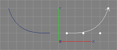
The Mirror object allows to easily create and control an arbitrary number of mirrored instances of a number of objects.[∗]
The original object(s) and their mirrored counterparts will be provided by the Mirror object to the respective parent object (normally, tool objects do not provide their unmodified children). Additionally, the order of the mirrored objects will be reversed so that it is possible to use a single Mirror object (with one or multiple NURBS curves as children) as parameter object of e.g. a Skin object:
+-Skin
  +-Mirror
    \-NCurve
+-Skin
  +-Mirror
    |-Curve_1(NCurve)
    |-Curve_2(NCurve)
    \-Curve_3(NCurve)
"NCurve_1", "NCurve_2", "NCurve_3", "Mirrored_NCurve_3",
"Mirrored_NCurve_2", "Mirrored_NCurve_1".
The following table briefly lists some capabilities of the Mirror object.
| Type | Parent of | Material | Converts to / Provides | Point Edit |
| Mirror | Any+ | No | Children+ | No* |
The following attributes control the mirror process:
"Plane" allows to select the plane about which the mirroring
should occur (YZ-, XZ-, or XY-plane).The Mirror object may be converted to ordinary objects using the
main menu entry "Tools/Convert".
Upon conversion a Level object will be created, that contains the original objects and the mirrored counterparts (the latter in reverse order).
Mirror objects appear in RIB output as a number of real objects, each with different transformation attributes.
The Select object may be used in hierarchies
of tool objects to select one object from a list of provided
objects.[∗]
Also multiple objects and ranges (even decreasing
ranges that lead to reversed orders) may be
selected.[∗]
In the following example hierarchy, a single patch from multiple provided patches of the Sweep object (the swept surface, a bevel, or a cap) could be selected by the Select object and delivered upstream to the ExtrNC object.
+-Sweep             <-----------------.
+-Revolve                             |
  +-ExtrNC                            |
    +-Select                          |
      \-Instance_of_Sweep(Instance) --'
The following table briefly lists some capabilities of the Select object.
| Type | Parent of | Material | Converts to / Provides | Point Edit |
| Select | Any+ | No | N/A / Children+ | No |
The following attribute controls the selection process:
"Indices" designates the object(s) to select. The index values
are zero based. Multiple indices must be separated by ",", ranges
can be specified like this "1-4", reversed ranges are allowed
("4-1") and will create an object list of reversed order. The special
index "end" (or abbreviated "e") designates the last of all
the provided objects.
An index may appear multiple times, leading to multiple copies of the
selected object to be delivered upstream.
The index space spans over all provided objects of the desired type
from all child objects. This means provided objects from multiple different
child objects of the Select object can be mixed. Syntactically incorrect
ranges and indices are silently ignored.
Examples:
"0,2" – delivers the first and third provided objects
upstream;"end-0" – delivers all provided objects in reversed order
upstream;"0,0,0" – delivers three copies of the first provided
object upstream;"0,4-end,1" – delivers the first, the fifth (if there are
so many) up to the last, and the second object upstream.Select objects never appear in RIB output.

RiInc objects draw a simple bounding box with stippled lines instead of the archive contents; those will only become part of the scene when it is exported to a RIB. See also the above image. If a RiInc object has children, they will be drawn instead of the bounding box. This allows to better convey the actual shape of the objects in the included archive.[∗] As the bounding box, also the children never appear in the RIB.
Note that Ayam can not check, wether the bounding box or children actually match the content of the included archive.
Also note that archives can be created easily using the main menu
entry
"Special/RIB-Export/Selected Objects".
The following table briefly lists some capabilities of the RiInc object.
| Type | Parent of | Material | Converts to / Provides | Point Edit |
| RiInc | Any | No | N/A | No |
The following attributes control the inclusion process:
"File" the filename of the RIB archive to be
included is specified."Width", "Height", and "Length" determine
the size of a box, that will be drawn as a geometric representation of
the RIB archive (if no children are present).RiInc objects export as single
ReadArchive <filename>
RiProc objects may be used to include procedural objects or external archives into your scenes. In contrast to archives included via a RiInc object, these archives will only be included by the RenderMan renderer when the specified bounding box is visible to the current camera.
The following table briefly lists some capabilities of the RiProc object.
| Type | Parent of | Material | Converts to / Provides | Point Edit |
| RiProc | No | No | N/A | No |
The following attributes control the RiProc object:
"Type" defines the type of the procedural object which is
one of "DelayedReadArchive", "RunProgram", or
"DynamicLoad"."File" you specify the filename of the RIB archive,
program, or dynamic shared object (depending on the type of the
procedural object)."Data" additional arguments may be supplied to
procedural objects of type "RunProgram" and "DynamicLoad"."MinX", "MaxX", "MinY", "MaxY", "MinZ",
and "MaxZ" specify the size of the bounding box of the objects that
the procedural will create or the archive contains.RiProc objects export as single
RiProcedural
These objects serve as geometric primitives in CSG hierarchies.
A solid box, centered at the origin of the object coordinate system.
The following table briefly lists some capabilities of the Box object.
| Type | Parent of | Material | Converts to / Provides | Point Edit |
| Box | No | Yes | NPatch∗ | No* |
The following parameters control the shape of the box:
"Width" is the width of the box (size of the box in
direction of the X-axis of the objects coordinate system)."Length" is the length of the box (size of the box in
direction of the Z-axis of the objects coordinate system)."Height" is the height of the box (size of the box in
direction of the Y-axis of the objects coordinate system).A box object may be converted to three NURBS patches
using the main menu entry
"Tools/Convert".[∗]
See section Cylindrical Box for a Script object that converts to a single NURBS patch.
The box object will always be exported as six bilinear patches.
A sphere, centered at the origin of the object coordinate system.
The following table briefly lists some capabilities of the Sphere object.
| Type | Parent of | Material | Converts to / Provides | Point Edit |
| Sphere | No | Yes | NPatch+ | No* |
The following parameters control the shape of the sphere:
"Closed" toggles whether the object should
be automatically sealed (closed by matching cap surfaces)."Radius" is the radius of the sphere, default is 1."ZMin" is the lower limit of the sphere on the Z-axis,
default is -1."ZMax" is the upper limit of the sphere on the Z-axis,
default is 1."ThetaMax" is the sweeping angle of the sphere in degrees, default
is 360.A Sphere object may be converted to NURBS patches
using the main menu entry "Tools/Convert". This conversion
obeys all parameters of the sphere.[∗]
If the sphere is closed, an enclosing Level object will be created and the caps follow the sphere in the following order: disk-shaped cap at zmin, disk-shaped cap at zmax, cap at theta 0, cap at thetamax.
The Sphere object appears in RIB output as simple
RiSphere(...);
"Closed" is enabled and "ZMin", "ZMax", or
"ThetaMax" have other than the default values,
as complex CSG hierarchy of at most two spheres, two cylinders, and
eight disks.
A disk in the XY-plane, centered at the origin of the object coordinate system.
The following table briefly lists some capabilities of the Disk object.
| Type | Parent of | Material | Converts to / Provides | Point Edit |
| Disk | No | Yes | NPatch | No* |
The following parameters control the shape of the disk:
"Radius" is the radius of the disk, default is 1."ZMin" displaces the disk along the Z-axis, default is 0."ThetaMax" is the sweeping angle of the disk in degrees,
default is 360.A Disk object may be converted to a NURBS patch
using the main menu entry "Tools/Convert". This conversion
obeys all parameters of the disk.[∗]
The Disk object will always be exported as simple disk:
RiDisk(...);
A cone, centered at the origin of the object coordinate system, with the base in the XY-plane.
The standard cone is always pointed. See section Truncated Cone for a Script object that implements a truncated cone.
The following table briefly lists some capabilities of the Cone object.
| Type | Parent of | Material | Converts to / Provides | Point Edit |
| Cone | No | Yes | NPatch+ | No* |
The following parameters control the shape of the cone:
"Closed" toggles whether the object should
be automatically sealed (closed by matching cap surfaces)."Radius" is the radius of the cone at the base, default is 1."Height" is the height of the cone, default is 1."ThetaMax" is the sweeping angle of the cone in degrees,
default is 360.A Cone object may be converted to NURBS patches
using the main menu entry "Tools/Convert". This conversion
obeys all parameters of the cone.[∗]
If the cone is closed, an enclosing Level object will be created and the caps follow the cone in the following order: disk-shaped cap at the base, cap at theta 0, cap at thetamax.
The Cone object appears in RIB output as simple
RiCone(...);
"Closed" is enabled and "ThetaMax" has a different than
the default value, as complex CSG hierarchy of at most one cone, one disk, and
two polygons.
A cylinder, centered at the origin of the object coordinate system.
The following table briefly lists some capabilities of the Cylinder object.
| Type | Parent of | Material | Converts to / Provides | Point Edit |
| Cylinder | No | Yes | NPatch+ | No* |
The following parameters control the shape of the cylinder:
"Closed" toggles whether the object should
be automatically sealed (closed by matching cap surfaces)."Radius" is the radius of the cylinder, default is 1."ZMin" determines the Z location of the base, default is -1."ZMax" determines the Z location of the top, default is 1."ThetaMax" is the sweeping angle of the cylinder in degrees,
default is 360.A cylinder object may be converted to NURBS patches
using the main menu entry "Tools/Convert". This conversion
obeys all parameters of the cylinder.[∗]
If the cylinder is closed, an enclosing Level object will be created and the caps follow the cylinder in the following order: disk-shaped cap at zmin, disk-shaped cap at zmax, cap at theta 0, cap at thetamax.
The cylinder object appears in RIB output as simple
RiCylinder(...);
"Closed" is enabled and "ThetaMax" has a different than
the default value, as complex CSG hierarchy of at most one cylinder, two disks,
and two polygons.
A torus, centered at the origin of the object coordinate system. A torus is a donut like shape, that results from sweeping a small circle (that has been displaced along X sufficiently) around the Z-axis.
The following table briefly lists some capabilities of the Torus object.
| Type | Parent of | Material | Converts to / Provides | Point Edit |
| Torus | No | Yes | NPatch+ | No* |
The following parameters control the shape of the torus:
"Closed" toggles whether the object should
be automatically sealed (closed by matching cap surfaces)."MajorRad" is the radius of the torus, measured
from the Z-axis to the center of the swept smaller circle, default is 0.75."MinorRad" is the radius of the swept circle, default is 0.25."PhiMin" determines an angle to limit the swept circle,
default is 0."PhiMax" determines an angle to limit the swept circle,
default is 360."ThetaMax" is the sweeping angle of the torus in degrees,
default is 360.A torus object may be converted to NURBS patches
using the main menu entry "Tools/Convert". This conversion
obeys all parameters of the torus.[∗]
If the torus is closed, an enclosing Level object will be created and the caps follow the torus in the following order: disk-shaped cap at theta 0, disk-shaped cap at thetamax, ring-shaped cap at phimin 0, ring-shaped cap at phimax.
The torus object appears in RIB output as simple
RiTorus(...);
"Closed" is enabled and "PhiMin", "PhiMax", or
"ThetaMax" have different than the default values, as complex
CSG hierarchy of at most one one torus, two disks, and two hyperboloids.
A paraboloid, centered at the origin of the object coordinate system.
The following table briefly lists some capabilities of the Paraboloid object.
| Type | Parent of | Material | Converts to / Provides | Point Edit |
| Paraboloid | No | Yes | NPatch+ | No* |
The following parameters control the shape of the paraboloid:
"Closed" toggles whether the object should
be automatically sealed (closed by matching cap surfaces)."RMax" is the radius of the paraboloid at a Z of "ZMax",
the base of the paraboloid surface, default is 1."ZMin" limits the paraboloid surface on the Z-axis,
must be positive, default is 0."ZMax" limits the paraboloid surface on the Z-axis and
determines the Z location of the base, must be positive, default is 1."ThetaMax" is the sweeping angle of the paraboloid in degrees,
default is 360.A paraboloid object may be converted to NURBS patches
using the main menu entry "Tools/Convert". This conversion
obeys all parameters of the paraboloid.[∗]
If the paraboloid is closed, an enclosing Level object will be created and the caps follow the paraboloid in the following order: disk-shaped cap at zmin, disk-shaped cap at zmax, cap at theta 0, cap at thetamax.
The paraboloid object appears in RIB output as simple
RiParaboloid(...);
"Closed" is enabled and "ZMin", "ZMax", or
"ThetaMax" have different than the default values, as complex
CSG hierarchy of at most one paraboloid, two disks, and two bicubic patches.
A hyperboloid, centered at the origin of the object coordinate system. The shape of the hyperboloid will be created by sweeping a line specified by two points in space around the Z-axis. Thus, disk, cylinder, and cone are special cases of the hyperboloid.
The following table briefly lists some capabilities of the Hyperboloid object.
| Type | Parent of | Material | Converts to / Provides | Point Edit |
| Hyperboloid | No | Yes | NPatch+ | No* |
The following parameters control the shape of the hyperboloid:
"Closed" toggles whether the object should
be automatically sealed (closed by matching cap surfaces)."P1_X", "P1_Y" and "P1_Z", define point one,
default is (0, 1, -0.5)."P2_X", "P2_Y" and "P2_Z", define point two,
default is (1, 0, 0.5)."ThetaMax" is the sweeping angle of the hyperboloid in degrees,
default is 360.A hyperboloid object may be converted to NURBS patches
using the main menu entry "Tools/Convert". This conversion
obeys all parameters of the hyperboloid.[∗]
If the hyperboloid is closed, an enclosing Level object will be created and the caps follow the hyperboloid in the following order: disk-shaped cap at P1, disk-shaped cap at P2, non-planar cap at theta 0, non-planar cap at thetamax.
The hyperboloid object appears in RIB output as simple
RiHyperboloid(...);
"Closed" is enabled and "ThetaMax" has a different than
the default value, as complex CSG hierarchy of at most one hyperboloid,
two disks, and two bilinear patches.
Note that due to a bug in BMRT that is still present in V2.3.6
the "Closed" option does not work properly when
"ThetaMax" has a different than the default value and the
hyperboloid has no displacement shader. In fact, using a displacement
shader with a km (amount of displacement) of 0.0 is a work-around
for this bug (found by T. E. Burge).
These objects are mainly used as child objects for the surface generating tool objects.
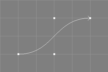
The NCurve object is the most used basic object for NURBS modelling in Ayam because NURBS curves are used to build more complex smoothly shaped surfaces using operations like extrude, revolve, sweep or skin. NURBS curves can be open or closed and used to emulate Bezier and B-Spline curves easily. In addition, for easier modelling, they support multiple points, as explained in section Multiple Points.
The following table briefly lists some capabilities of the NCurve object.
| Type | Parent of | Material | Converts to / Provides | Point Edit |
| NCurve | No | No | N/A | Yes |
NCurve objects may be created via the toolbox, the main menu, several tools as documented in section Curve Creation Tools, or the scripting interface, see also sections Creating Objects
Tools that process NCurve objects are documented in Curve Modification Tools.
The next section details the NCurve object attribute property.
The first section of the NCurveAttr property contains curve specific settings:
"Type": This attribute replaces the "Closed"
attribute since Ayam 1.9.
The type "Open" is for the standard open NURBS curve.
If the type is "Closed", the first and last control point of
the curve will be made identical. This will close the curve but
without any guaranteed continuity.
Such a closed curve will e.g. be created by the NURBS circle tool.
It is important to know, that identical start/end control points
alone can not guarantee that the curve is closed if the knot vector
is not clamped. If in doubt, use the clamp tool or a knot vector
of type "NURB", "Chordal", or "Centripetal".
If the type is "Periodic", the last p control points of the curve
will be made identical to the first p where p is the degree of the
curve (read order-1). This will close the curve with guaranteed continuity.
Note that for a cubic spline (order 4) you will need at least 6 control
points to make it periodic. It is important to know, that the multiple control
points alone can not guarantee that the curve is closed if the knot vector
has no periodic extensions. If in doubt, switch the curve to
knot type "B-Spline", "Chordal", or "Centripetal".
You may also want to enable the creation of multiple points using the
"CreateMP" attribute (see below) for closed and periodic curves so that
single point editing actions modify all multiple control points.
"Length" is the number of control points of the curve.
"Order" is the order of the curve, determining how many
control points influence a given point on the curve.
The order further constraints the level of achievable continuity.
Common values range from two to five. An order of two lets
the curve degenerate to a polygon."Knot-Type": The knot type of a NURBS curve can be set to be any of
"NURB", "Bezier", "B-Spline", "Custom", "Chordal",
and "Centripetal".
The knot type "NURB" will generate uniformly distributed knot values
ranging from 0.0 to 1.0, where the multiplicity of the knots at the
ends will be of order of the curve (the knot vector will be clamped).
This guarantees that the curve will touch the control points at the ends
of the curve.
An example "NURB" knot vector for a curve of length 5 and order 4
would be:
{ 0.0 0.0 0.0 0.0 0.5 1.0 1.0 1.0 1.0 }.
The knot type "Bezier" will generate just 0.0 and 1.0 values. Note that
the order of the curve has to be equal to the length of the curve if
"Bezier" knots are generated. Otherwise, the generated knot sequence is
illegal. The resulting curve looks and behaves exactly like a real
Bezier curve, interpolating the control points at the ends and so on.
An example "Bezier" knot vector for a curve of length 5 and order 5
would be:
{ 0.0 0.0 0.0 0.0 0.0 1.0 1.0 1.0 1.0 1.0 }.
The knot type "B-Spline" will generate uniformly distributed knot values
(without any multiple knots). The resulting curve looks and behaves like a
B-Spline curve. It is not interpolating the control end points.
An example "B-Spline" knot vector for a curve of length 5 and order 4
would be:
{ 0.0 0.125 0.25 0.375 0.5 0.625 0.75 0.875 1.0 }.
The knot type "Custom" allows to set a manually specified knot
vector not like e.g. :
{ 0.0 0.0 0.0 1.0 2.0 3.0 }.
The knot types "Chordal" and "Centripetal" will generate knot
values whose distribution reflect the distances of the control points.
However, this only works, if there are free knots in the knot vector,
i.e. knots that are not subject to clamping or periodic extensions.
For example, the default NURBS curve with four control points and order
four has no free knots.
For open curves, the generated knot vector will be clamped, for periodic
curves, proper periodic extensions will be created.
Those knot types are mainly useful for curves with unevenly distributed
control points that will be sampled uniformly (in parametric space) later
on and where it is expected, that the uniform sampling in parameter space
results in evenly distributed sample points in coordinate space, e.g. if
the curves are used as Sweep, Birail, or Clone trajectory, or surfaces
are created from them that use implicit texture coordinates or a uniform
tesselation strategy.
The "Chordal" and "Centripetal" knots will ensure a more uniform
distribution of the sample points on the curve in such cases (see also the
example image below) while retaining complete freedom of control point
placement.
An example "Chordal" knot vector for an open curve of length 5 and
order 4 would be:
{ 0.0 0.0 0.0 0.0 0.388889 1.0 1.0 1.0 1.0 }.
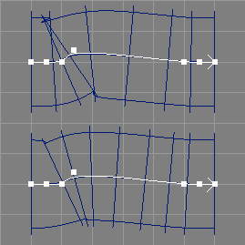
The image below illustrates the use of two curves with uniform (NURB) vs. chordal knot vectors as Sweep trajectories. The upper Sweep with the uniform knot vector has much more unevenly distributed/sized sections and exhibits more severe self intersection problems. Please note that the shapes of the curves differ slightly.
"Knots" allows to enter own custom knot sequences.
Note that this only works if the "Knot-Type" (above)
is "Custom". Otherwise, the "Knots" parameter just displays
the automatically generated knot sequence and changes to the values
have no effect.
Each knot vector has l+o knot values, where l is the length of the curve and o its order. The knot values must be strictly monotonous increasing and the maximum number of equal values in a row must not exceed the order of the curve.
"CreateMP" toggles, whether multiple points should be
created for this curve. See also the discussion in
section
Multiple Points.
"IsRat" informs, whether the curve
is rational (has any weight values different from
1.0).[∗]The GLU-parameters control the appearance of the curve when curve/surface display is enabled.
"Tolerance" is in fact GLU sampling tolerance, used to
control the quality of the sampling when rendering a curve.
Smaller tolerance settings lead to higher quality but also
slower display.
A setting of 0.0 means, that the global preference setting
"Drawing/Tolerance" should be used.
"DisplayMode" determines how the curve should
be drawn. The control hull (control polygon) or the curve or a
combination of both may be displayed. The setting "Global"
means, that the global preference setting
"Drawing/NCDisplayMode" should be used.
When changing more than one of the above values the changes will be
applied in the order of the values in the property. The
sum of the changed values should describe a valid NURBS curve.
It is perfectly legal to change the length of the curve,
it's order, and switch to a custom knot vector (be sure to actually
enter a valid new knot vector) at once. Ayam will check your changes
and fall back to certain default values if e.g. your knot sequence is wrong.
Check the console for any messages after pressing the "Apply" button!
When the curve type is changed using the NCurveAttr property Ayam may also have to change the position of some control points as follows:
"Open" to "Closed",
the last control point is moved to be identical to the first one.
In addition, if the current knot type of the curve is "B-Spline",
it will be reset to knot type "NURB"."Open" or "Closed" to
"Periodic", the last
p control points will be moved to be identical to the first p, where
p is the degree of the curve (order-1). For a cubic curve (order 4),
consequently, the last three control points will be moved. In addition,
if the current knot type of the curve is "NURB" or "Bezier"
it will be changed to "B-Spline" automatically.Note that there are also specialized tools for curve type management
in the "Tools/Curve" sub-menu
that can be used to avoid unwanted modification,
offer more control, and preview;
see sections
Open Tool and
Close Tool.
When changing the order of a periodic curve (and not touching the length) Ayam will automatically add or remove control points to/from the curve so that the shape of the curve remains largely intact and the periodic extensions plausible.[∗]
Note that there are also specialized tools for curve order management
in the "Tools/Curve" sub-menu that can be used to
avoid unwanted changes, offer more control, and preview;
see sections
Elevate Tool and
Reduce Tool.
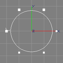
The NURBS curves of Ayam support so called multiple points.
A multiple point is made of a number of different control points
that have the same coordinates. Multiple points will be drawn with a
bigger handle than normal points (see image above).
Single point interactive modelling actions (e.g. edit) will always
modify all the control points that make up a multiple point.
Selecting/tagging a multiple point will always select all control points
of that multiple point.
Modelling actions that work with selected points (e.g. translate)
will only modify all control points of a multiple point, if it is
completely selected. This selection state is conveyed by drawing
a completely filled bigger handle.[∗]
Individual points of a multiple point may be selected by
"CreateMP" property of the curve,"selPnts" scripting interface command"CVView" propertyMultiple points may also be created using the collapse tool, and split up again using the explode tool (see sections Collapse Tool and Explode Tool for more information regarding those tools).
NCurve objects never directly appear in RIB output (only indirectly as trim curve).
To create NCurve objects using the scripting interface see
section
crtOb NCurve command.
For scripting interface commands that manipulate NURBS curve objects
see section
Manipulating NURBS Curves.
The ICurve object creates a global interpolating NURBS curve from n 3D non-rational ordered data points. The curve may be open or closed, the order of the curve may be configured, the parameterisation may be adapted, and end derivatives may be specified. The open versions create n+2 NURBS control points, and the closed ones n+3.

The image above shows some interpolating curves, the left ones
are of order 3 (quadratic curves), the right ones are of order 4 (cubic
curves), the upper open, and the lower closed ones. The interpolation
fidelity for the closed curves was tuned by adjusting the "SDLen"
and "EDLen" parameters (all set to 0.2), see also the discussion
of the parameters below.
In all parameterisation modes, knot averaging will be used to determine the knot vector of the interpolating curve.
Note that the axis of symmetry for closed interpolating curves crosses the first data point (in contrast to open interpolating or closed approximating curves, where it crosses between the last and first data point). For example, the closed interpolating curves in the above example image are indeed both symmetric, but the axis of symmetry is crossing the first and third data point and is, thus, rotated by 45 degrees.
This object makes use of the provide mechanism. It marks itself as providing a NCurve object (it creates and uses NURBS curves internally anyway) and all other objects that work with the provide mechanism (e.g. revolve, sweep, extrude, and skin) are able to work with an ICurve object instead of an object of type NCurve.
The following table briefly lists some capabilities of the ICurve object.
| Type | Parent of | Material | Converts to / Provides | Point Edit |
| ICurve | No | No | NCurve | Yes |
ICurve objects may be created via the toolbox, the main menu, or the scripting interface, see also Creating Objects.
The following parameters control the interpolation process:
"Type" parameter controls whether the interpolated
curve should be open or closed.
"Length" is the number of data points to interpolate.
"Order" determines the desired order of the
interpolating curve. If the specified order is bigger than the number of
control points used by the interpolating NURBS curve, then the order is
silently changed to match the number of control points.
"ParamType" switches the parameterisation
between "Chordal" (default), "Centripetal", and "Uniform".
The centripetal method generates a better parameterisation than
the default (chordal) if the input data contains sharp turns.
The uniform method is available since Ayam 1.20 and generates
worse parameterisations (that lead to wiggles and overshooting)
in the general case but it might help in some edge cases.
"Derivatives" allows to choose between automatic and
manual derivatives.
If automatic derivatives are switched on, the direction of the derivatives
will be determined from the first, second, second to last, and last
data points for open curves and from the second and second to last data
points for closed curves. In addition, the respective derivative
vector will be scaled by "SDLen" and "EDLen".
If manual derivatives are switched on, two more
editable points appear in the single point editing modes. Those
additional points directly control the derivatives for the
endpoints of the interpolating curve. The parameters "SDLen" and
"EDLen" do not influence those derivatives.
"SDLen" and "EDLen" are used to control
the length of the first and last derivative (if automatically
generated from the data points, i.e. when "Derivatives" above is
switched to automatic).
"Tolerance" and "DisplayMode"."NCInfo" field informs about the actual configuration
of the created NURBS curve.The parameters "Mode", "Closed", and "IParam" are gone
since Ayam 1.16. "Closed" was replaced by "Type", "IParam"
by "SDLen" and "EDLen", and the "Mode" is now determined
automatically from the desired order.
See also the related tool to create interpolating NURBS curves: Interpolate Tool.
The interpolating curve may be converted to an ordinary NURBS curve using the
main menu entry "Tools/Convert".
ICurve objects never directly appear in RIB output (only indirectly as trim curve).
To create ICurve objects using the scripting interface see
section
crtOb ICurve command.

The ACurve object creates an approximating NURBS curve with m control points from n 3D non-rational ordered data points (see image above).[∗]
The number of desired output control points must be smaller than or equal to the number of data points to approximate (m≤n). The approximation algorithm used is of the least squares variety. If the number of control points approaches the number of data points, undesired wiggles in the output curve may occur.
This object makes use of the provide mechanism. It marks itself as providing a NCurve object (it creates and uses NURBS curves internally anyway) and all other objects that work with the provide mechanism (e.g. Revolve, Sweep, Extrude, and Skin) are able to work with an ACurve object instead of an object of type NCurve.
The following table briefly lists some capabilities of the ACurve object.
| Type | Parent of | Material | Converts to / Provides | Point Edit |
| ACurve | No | No | NCurve | Yes |
ACurve objects may be created via the main menu or the scripting interface, see also Creating Objects.
The following parameters control the approximation process:
"Length" determines the number of data points to
approximate.
"ALength" is the number of (distinct)
control points to use for the approximating NURBS curve.
The total number of distinct control points must be smaller than or equal
to the number of data points.
"Closed".
For closed approximations, the total number of control points will
be "ALength + Order - 1".
The following table illustrates this relationship.
| Length | ALength | Order | Closed | Output Length |
| 10 | 5 | 3 | No | 5 |
| 10 | 5 | 3 | Yes | 8 |
| 10 | 4 | 4 | Yes | 8 |
| 5 | 4 | 3 | No | 4 |
| 5 | 4 | 3 | Yes | 7 |
"Symmetric"
a symmetric result can be enforced (see image below), albeit at the
cost of about double runtime and a slightly worse parameterisation.
For closed symmetric curves, "ALength" must be smaller than
"Length".[∗]
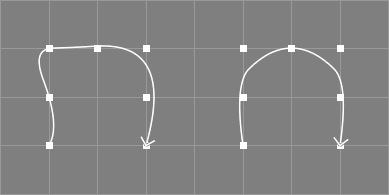
"Order" specifies the desired order
of the approximating NURBS curve. Currently, only orders higher than
2 are supported.
"Tolerance" and "DisplayMode"."NCInfo" field informs about the actual configuration
of the created NURBS curve.See also the related tool to approximate existing NURBS curves: Approximate Tool.
The approximating curve may be converted to an ordinary NURBS curve using the
main menu entry "Tools/Convert".
ACurve objects never directly appear in RIB output (only indirectly as trim curve).
To create ACurve objects using the scripting interface see
section
crtOb ACurve command.
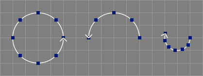
The NCircle object creates a circular NURBS curve or a circular arc in the XY-plane centered at the origin with designated radius and start/end angles (see image above).[∗]
A full circle is created using nine rational control points in a rectangular configuration, circular arcs are created with fewer control points. See section NURBS Circle with Triangular Base for a Script object that implements a circle with less control points.
In order to revert the created NURBS curve
the start/end angles may be used, e.g. "TMin" 0.0,
"TMax" -360.0 for a reverse full circle.[∗]
The following table briefly lists some capabilities of the NCircle object.
| Type | Parent of | Material | Converts to / Provides | Point Edit |
| NCircle | No | No | NCurve | No* |
The following parameters control the shape of the circle or arc.
"Radius" is the radius of the circle.
"TMin" (ThetaMin) controls the starting angle of the circle
or arc to be created. Negative values are allowed.
"TMax" (ThetaMax) controls the end angle of the circle
or arc to be created. Negative values are allowed.
"Tolerance" and "DisplayMode"."NCInfo" field informs about the actual configuration
of the created NURBS curve.The circular curve/arc may be converted to an ordinary NURBS curve using the
main menu entry "Tools/Convert".
NCircle objects never directly appear in RIB output (only indirectly as trim curve).
More basic curve types are available via plugins and scripts, those are:
These objects modify existing curves or create new curves.

The ConcatNC object concatenates all child objects (which should be NURBS curves or provide NURBS curves) to a single NURBS curve. Since the ConcatNC object also provides a NURBS curve, it is possible to use it as child object for another ConcatNC object (with possibly different parameters) or as a parameter object for a tool object that works with NURBS curves such as Revolve or Extrude.
The concatenation process works as follows:
"FillGaps" is enabled, fillet curves will be
created for every gap between the parameter curves of the ConcatNC object.
If "Closed" and "FillGaps" are enabled, an additional fillet
is created to close the curve."Closed" is enabled, the curve will be closed.The knot sequence of the new concatenated curve will be of type
"NURB" or a custom knot vector will be computed (depending
on the setting of "Knot-Type").
If "Knot-Type" is "NURB", the shape of the concatenated curve
will differ from the parameter curves if any of the parameter curves has
a custom knot vector with non equidistant knots.
If "Knot-Type" is "Custom", the shape of the parameter curves
will be preserved completely, but the knot vector of the concatenated
curve will then contain internal multiple knots.
Attributes like display mode and tolerance for the new concatenated curve are simply taken from the first parameter curve.
For best results, only clamped curves should be used as parameter objects.
The following table briefly lists some capabilities of the ConcatNC object.
| Type | Parent of | Material | Converts to / Provides | Point Edit |
| ConcatNC | NCurve+ | No | NCurve | No* |
The following parameters control the concatenation process:
"Closed" a closed concatenated curve may be created,
even if the parameter curves do not touch.
If also "FillGaps" (see below) is enabled, an additional fillet will
be created for the last and the first child curve to close
the concatenated curve. If "FillGaps" is not enabled,
the concatenated curve will be closed with the same algorithm
that is also used by the close curve tool (possibly changing
its shape).
"Revert" is enabled, the orientation of the concatenated
curve will be reversed.
"FillGaps" creates fillet curves for all gaps between
the parameter curves of the ConcatNC object. No fillet will be created
if the end points of two parameter curves match.
The fillet curves will initially be created from four control
points. The outer fillet control points are the parameter curve end points
and the inner fillet control points will be positioned on the tangent
of the respective parameter curve end point (see also the discussion
of "FTLength" below). Thus, the transitions between parameter
curve and fillet should be at least G1 continuous.
Degree elevation will be used to raise the degree of the fillet to
that of the concatenated curve; this may introduce additional
control points in the fillet but its shape does not change and the
transition continuity is also not affected.
If the order of the resulting concatenated curve is 2, only simple fillets, connecting the parameter curves by straight lines, will be generated.
"FTLength" determines the distance of the inner fillet
control points from their respective end points. This value can
be adapted for smaller/larger gaps between parameter
curves.
If the "FTLength" parameter is 0.0, C1 continuous fillets will
be created by global curve interpolation instead of the G1 fillets
outlined above.
"Knot-Type" sets the knot type of the concatenated curve:
"Knot-Type" is "NURB" a simple knot vector
with equidistant knots is generated, which leads to a concatenated curve
that does not exactly preserve the shapes of the original curves if any
of the parameter curves has a custom knot vector with non equidistant knots.
Furthermore, all transitions between parameter curves are always smoothed
out.
"Knot-Type" is "Custom", the knot vector is composed from
the knot vectors of the original curves, and thus, their
shapes may be preserved completely. Note, that potential discontinuities
of any level, even gaps between the parameter curves are also fully
preserved.
However, this comes at the price of internal multiple knots. A problem with these knots is, that the resulting curve is not differentiable in these places anymore, which in turn can be problematic for operations like sweeps.
"NCInfo" field informs about the actual configuration
of the created NURBS curve.The concatenated curve may be converted to an ordinary NURBS curve using the
main menu entry "Tools/Convert".
ConcatNC objects never directly appear in RIB output (only indirectly as trim curve).
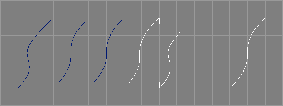
The ExtrNC object extracts a NURBS curve from a NURBS patch object, for use as parameter object for other tool objects, like e.g. Revolve (see image above). It also works with NURBS patch providing objects, so that the following example hierarchy is valid:
|-NPatch   <-------------------------.
+-Skin                               |
  +-ExtrNC                           |
  | \-Instance_of_NPatch(Instance) --'
  \-NCurve
"Tools/Create/ExtrNC"
will automatically create an instance of the currently selected object
and move it to the newly created ExtrNC object.
As the geometry of the extracted curve is completely defined by the master surface, ExtrNC objects do not support own transformation attributes.[∗]
Note that the extraction of any curves currently completely ignores
potentially present trimming information of the NPatch object, i.e. the
extracted curves will not be trimmed.
However, complete trim boundaries may be
extracted.[∗]
The following table briefly lists some capabilities of the ExtrNC object.
| Type | Parent of | Material | Converts to / Provides | Point Edit |
| ExtrNC | NPatch | No | NCurve | No* |
The extraction process is controlled by the following attributes:
"Side" controls which curve should be extracted from the
surface.
Available values are:
"U0", "Un": extract upper or lower
boundary curve (along width);"V0", "Vn": extract left or right
boundary curve (along height);"U", "V"
extract curve along width and height respectively at specified parametric
value (see below).[∗]"Boundary": extract the complete boundary curve of the
patch, by extracting four boundary curves, automatically selecting the
proper method depending on the knot type of the surface
(e.g. "U0" or "U"), reversing two and concatenating all non
degenerated curves to the result.[∗]"Middle_U", "Middle_V": create a curve from the patch
data that is the "middle axis" (simply the medium of all control points
of a patch in the designated
dimension).[∗]"Trim", all trim curves and loops of the current patch will
appear here.[∗]
Note, that their extraction will result in an approximation
of the 3D representation of the corresponding trim boundary only. In
particular, the extracted curve will not be compatible to the trim curve.
The approximation quality can be adjusted using "Parameter" (see below)."Side" is "U0", "Un", "V0", or "Vn"
the extraction process just copies the respective boundary control points,
which is fast but only works correctly for clamped knot vectors. To extract
a boundary from a surface with e.g. a B-Spline knot vector, "U0" should
not be used but rather "U" with "Parameter" set to 0.0 and
"Relative" enabled as "U" uses a different, more expensive,
extraction process (which involves knot insertion).
"Parameter" controls the parametric value in U or V
direction in the parameter space of the NURBS patch object where the
curve should be extracted or the approximation quality of extracted
trim curves. Consequently, this parameter is only used when "Side"
is "U", "V" or "Trim".
The valid range of parameter values depends
on the knot vectors of the NURBS patch."Drawing/Tolerance":
smaller values lead to dense sampling and higher quality, the useful
range of values is 0.01 to 100.
"Relative" controls whether or not the parametric value delivered
via "Parameter" above should be interpreted in a relative way.
If enabled, a parametric value of 0.5
always extracts from the middle of the knot vector / surface,
regardless of the actual knot values, and the valid range
for "Parameter" is
then consequently 0.0-1.0.[∗]
"Revert" immediately reverts the extracted curve.
"CreatePVN" controls creation of a PV or NT tag that contains
just the normals or normals and tangents on the surface.
These tags can then be used to e.g. control a 3D offset curve.
The normals and tangents will be derived from the surrounding
surface control points except for trim boundary extraction where
the underlying surface will be evaluated exactly.
Note that the tag will be present on provided/converted curve objects only.
When extracting a middle axis, this option is ignored.
"PatchNum" allows to select a patch from a list of
patches delivered e.g. by a beveled Extrude object as child
of the ExtrNC object.
This way it is possible to extract a curve from a bevel or cap
surface of e.g. said Extrude object."NCInfo" field informs about the actual configuration
of the extracted NURBS curve.See section
NCurveAttr for a description
of the other two attributes "DisplayMode" and "Tolerance".
The extracted curve may be converted to an ordinary NURBS curve using the
main menu entry "Tools/Convert".
ExtrNC objects never directly appear in RIB output (only indirectly as trim curve).
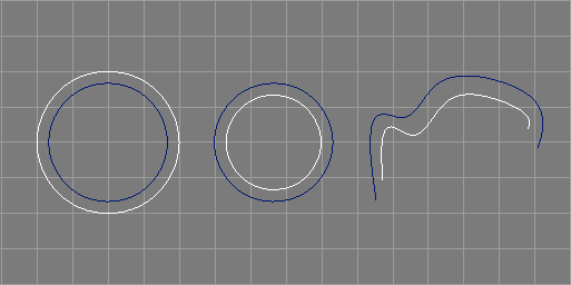
The OffsetNC object creates offset curves from planar NURBS curves using
different algorithms.[∗]
See also the image above.
The offset curve will always match the original curve in type, length, order, and knots. No attempt is made to prevent collisions or self intersections. Rational curves are not supported well.
The available offset algorithms are:
Point
offsets each control point along the normal derived from the surrounding
control points; the offset curve created by this algorithm may come too
near the original curve at sharp convex features whose exact forms are
not preserved well either,
Section
this algorithm offsets all control polygon sections in the direction of their
normal and places new control points at intersection points of the lines
defined by the offset sections; this algorithm is better in avoiding self
intersections of the offset curve but the offset curve may be too far away
from the original curve at sharp convex or concave features
(regions of high curvature),
Hybrid
this algorithm offsets the curve two times using the Point and Section
algorithms and then mixes the results so that the bad
features of the two algorithms cancel out each
other,[∗]
3DPVN [∗]
this algorithm
creates true three dimensional offsets from non planar curves using
a primitive variable tag that contains normal information for the curve
(vertex normals). Such tags can be created manually or automatically
e.g. when extracting curves from surfaces using the "ExtrNC" object.
3DPVNB
Three dimensional offset like 3DPVN above, but offsets in the
direction of the binormal.[∗]
PlaneNormal [∗]
this algorithm
creates true three dimensional offsets from planar curves using
the mean normal of the plane, the curve is defined in. Since all points
are moved by the same amount, the shape and planarity of the curve will
be preserved.
As the geometry of the offset curve is completely defined by the master curve and the offset parameter, OffsetNC objects do not support own transformation attributes.[∗]
The "Bevel3D" offset algorithm has been removed since Ayam 1.19.
The following table briefly lists some capabilities of the OffsetNC object.
| Type | Parent of | Material | Converts to / Provides | Point Edit |
| OffsetNC | NCurve | No | NCurve | No* |
The following parameters control the offsetting process:
"Mode" determines, which algorithm
to use for the offsetting process.
"Revert" the direction of the offset curve may be reversed.
"Offset" determines the distance between original curve and
offset curve. Negative values are allowed.
"Tolerance" and "DisplayMode"."NCInfo" field informs about the actual configuration
of the created NURBS curve.The offset curve may be converted to an ordinary NURBS curve using the
main menu entry "Tools/Convert".
OffsetNC objects never directly appear in RIB output (only indirectly as trim curve).
These objects enable direct manipulation of freeform surfaces.
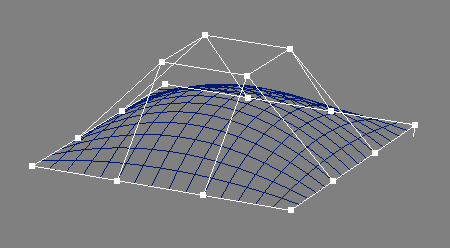
The NPatch object allows to model NURBS surfaces in a direct way, e.g. by modifying control points (see also the image above). Note that using NPatch objects should be seen as last resort, only to be used when the flexibility of all the NURBS surface creating tool objects is not sufficient to achieve a certain shape.
Like NCurve objects, NPatch objects mark their last control point with a small arrow. Note that the arrow points in the V direction (height).
NPatch objects also support the concept of multiple points, see section Multiple Points for more information regarding this.[∗]
The following table briefly lists some capabilities of the NPatch object.
| Type | Parent of | Material | Converts to / Provides | Point Edit |
| NPatch | NCurve+/ Level+ | Yes | PolyMesh | Yes |
NPatch objects may be created via the toolbox, the main menu, some tools as documented in section Surface Creation Tools, or the scripting interface, see also Creating Objects.
Tools that process NPatch objects are documented in section Surface Modification Tools.
The first section of the NPatchAttr property contains patch specific settings:
"Width" and "Height" control the dimensions of the patch.
Similar to the "Length" parameter of the NCurve object, changes to
"Width" or "Height" add or remove internal control points
(i.e. to double the resolution of a 4 by 4 NURBS patch in U direction,
change the "Width" from 4 to 7; this will lead to an additional
control point inserted into every section of the original patch).
"Order_U" and "Order_V" set the orders of the patch.
"Knot-Type_U"/"Knot-Type_V" and
"Knots_U"/"Knots_V": For a discussion of the
"Knot-Type" and "Knots" parameters,
please see section
NCurveAttr.
"CreateMP" toggles, whether multiple points should be
created for this surface. See also the discussion in
section
Multiple Points.[∗]
"IsRat" informs, whether the patch
is rational (has any weight values different from
1.0).[∗]The next parameters control the appearance of the patch for display in Ayam:
"Tolerance" is in fact the GLU sampling tolerance used to
control the quality of the sampling when rendering the patch.
Smaller tolerance settings lead to higher quality but also
slower display.
A setting of 0.0 means, that the global preference setting
"Drawing/Tolerance" should be used.
"DisplayMode" sets the display mode, either the control
hull is drawn ("ControlHull"), or just the outlines of the polygons
created by the tesselation ("OutlinePolygon"), or just the
outlines of the patch ("OutlinePatch"). The default setting
("Global") means, that the value of the global preference setting
"Drawing/NPDisplayMode" should be used instead.
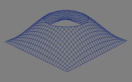
"Trim", that draw the boundaries of the parametric
space of the corresponding NURBS patch as rectangle, but otherwise
act as normal "Front" views.
Note that the direction of the trim curve determines which part of
the NURBS patch should be cut out. The Revert tool
("Tools/Curve" menu) can be used to easily change the direction
of a trim curve.
Some special restrictions apply to trim curves:
Trim view).
Note that this restriction does not apply to the control points,
but the curves! It is ok to have control points outside the
rectangle if the defined curve is inside the rectangle.
TrimRect tool. This tool can be found in
the "Tools/Create" menu. This curve is needed if you want to cut
out a hole with a single trim curve. This curve is generally not needed
if you want to render the patch with BMRT but it should not hurt if it
is present.
Warning: Certain OpenGL implementations may be easily crashed drawing trimmed NURBS patches with trims that do not follow the aforementioned rules. When in doubt or while heavy modelling, switch to wire-frame drawing and switch off shading temporarily and you will be on the safe side.
NURBS curve providing objects are also supported as trim curves.[∗] When objects provide multiple NURBS curves, those do not form a single loop, but are seen as individual loops.
The NPatch object supports the standard caps as lined out in section
Caps Property
and the standard bevels as lined out in section
Bevels Property.
The boundary names are U0, U1, V0, and V1.
Integration is not supported; the corresponding option is silently ignored.
A NPatch object may be converted to a PolyMesh object using the
main menu entry "Tools/Convert".
This process is also called tesselation and thus, the tesselation parameters from TP tags will be used in the conversion process (if present) (see also section TP Tag).
If bevels or caps are present, an enclosing Level object will be created and the tesselated bevels or caps follow the tesselated NPatch in the following order: U0, U1, V0, V1.
NPatch objects will be exported as NURBS patch primitives:
RiNuPatch(...);
Multiple TC tags are also supported.[∗]
To create NPatch objects using the scripting interface see
section
crtOb NPatch command.
For scripting interface commands that manipulate NURBS patch objects
see section
Manipulating NURBS Surfaces.
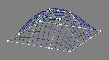
An IPatch forms a surface defined by interpolating a regular grid of three dimensional and non rational data points (see also the image above).
The following table briefly lists some capabilities of the IPatch object.
| Type | Parent of | Material | Converts to / Provides | Point Edit |
| IPatch | No | Yes | NPatch | Yes |
IPatch objects may be created via the main menu or the scripting interface, see also Creating Objects.
The IPatchAttr property contains the following elements:
"Width" and "Height" control the dimensions of the patch.
Similar to the "Length" parameter of the NCurve object, changes to
"Width" or "Height" add or remove internal control points
(i.e. to double the resolution of a 4 by 4 interpolating patch in U direction,
change the "Width" from 4 to 7; this will lead to an additional
control point inserted into every section of the original patch).
"Order_U" and "Order_V" set the desired interpolation
orders of the patch. If any of these values is set to 2, no explicit
interpolation will take place in this dimension (the surface will
implicitly interpolate the data points due to the low order).
"Close_U" and "Close_V" allow to create closed
surfaces in the respective dimension.
"Knot-Type_U" and "Knot-Type_V" switches the parameterisation
between "Chordal" (default), "Centripetal", and "Uniform".
The centripetal method generates a better parameterisation than
the default (chordal) if the input data contains sharp turns.
The uniform method generates worse parameterisations (that lead to
wiggles and overshooting)
in the general case but it might help in some edge cases.
"Deriv_U" and "Deriv_V" toggle whether
"None": no end derivatives,
"Automatic": automatically created (from data points)
derivatives, scaled by the additional parameters
"SDLen_U", "EDLen_U", "SDLen_V", and"EDLen_V",
"Manual": completely manually controlled end derivatives
(appearing as additional control points in point editing, if enabled)The next parameters control the appearance of the patch for display in Ayam:
"Tolerance" is in fact the GLU sampling tolerance used to
control the quality of the sampling when rendering the patch.
Smaller tolerance settings lead to higher quality but also
slower display.
A setting of 0.0 means, that the global preference setting
"Drawing/Tolerance" should be used.
"DisplayMode" sets the display mode, either the control
hull is drawn ("ControlHull"), or just the outlines of the polygons
created by the tesselation ("OutlinePolygon"), or just the
outlines of the patch ("OutlinePatch"). The default setting
("Global") means, that the value of the global preference setting
"Drawing/NPDisplayMode" should be used instead."NPInfo" field informs about the actual configuration
of the created NURBS patch.See also the related tool to create interpolating NURBS surfaces: Interpolate Surface Tool.
The IPatch object supports the standard caps as lined out in section
Caps Property
and the standard bevels as lined out in section
Bevels Property.
The boundary names are U0, U1, V0, and V1.
The interpolated surface may be converted to an ordinary NURBS patch
using the main menu entry
"Tools/Convert".
IPatch objects will be exported as NURBS patch primitives:
RiNuPatch(...);
Multiple TC tags are also supported.[∗]
To create IPatch objects using the scripting interface see
section
crtOb IPatch command.
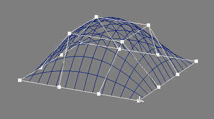
An APatch forms a surface defined by approximating a regular grid of three dimensional and non rational data points (see also the image above).[∗] The approximation will occur first in U then in V direction, first in V then in U direction, just in U, or just in V direction.
The following table briefly lists some capabilities of the APatch object.
| Type | Parent of | Material | Converts to / Provides | Point Edit |
| APatch | No | Yes | NPatch | Yes |
APatch objects may be created via the main menu or the scripting interface, see also Creating Objects.
The APatchAttr property contains the following elements:
"Width" and "Height" control the number of data
points of the patch to approximate.
Similar to the "Length" parameter of the NCurve object, changes to
"Width" or "Height" add or remove internal control points
(i.e. to double the resolution of a 4 by 4 approximating patch in U direction,
change the "Width" from 4 to 7; this will lead to an additional
control point inserted into every section of the original patch).
"Mode" determines the order in which the partial approximations
occur.
"AWidth" and "AHeight" set the desired number of
NURBS control points. Both values must be smaller or equal to
"Width" and "Height" respectively.
"Order_U" and "Order_V" set the desired approximation
orders of the patch.
"Knot-Type_U" and "Knot-Type_V" switches the parameterisation
between "Chordal" (default) and "Centripetal".
The centripetal method generates a better parameterisation than
the default (chordal) if the input data contains sharp turns.
If the approximation mode is "U" or "V" more knot types will
be available for the dimension where no approximation occurs.
Those knot types are: "Bezier", "B-Spline", and "NURB".
See section
NCurveAttr Property for their
documentation.
"Close_U" and "Close_V" allow to create closed
surfaces in the respective dimension.
The next parameters control the appearance of the patch for display in Ayam:
"Tolerance" is in fact the GLU sampling tolerance used to
control the quality of the sampling when rendering the patch.
Smaller tolerance settings lead to higher quality but also
slower display.
A setting of 0.0 means, that the global preference setting
"Drawing/Tolerance" should be used.
"DisplayMode" sets the display mode, either the control
hull is drawn ("ControlHull"), or just the outlines of the polygons
created by the tesselation ("OutlinePolygon"), or just the
outlines of the patch ("OutlinePatch"). The default setting
("Global") means, that the value of the global preference setting
"Drawing/NPDisplayMode" should be used instead."NPInfo" field informs about the actual configuration
of the created NURBS patch.The APatch object supports the standard caps as lined out in section
Caps Property
and the standard bevels as lined out in section
Bevels Property.
The boundary names are U0, U1, V0, and V1.
The approximating surface may be converted to an ordinary NURBS patch
using the main menu entry
"Tools/Convert".
APatch objects will be exported as NURBS patch primitives:
RiNuPatch(...);
Multiple TC tags are also supported.
To create APatch objects using the scripting interface see
section
crtOb APatch command.
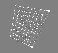
A BPatch is a simple bilinear patch defined by four control points. BPatch objects are e.g. used internally to build box objects, see also Box Object.
The following table briefly lists some capabilities of the BPatch object.
| Type | Parent of | Material | Converts to / Provides | Point Edit |
| BPatch | No | Yes | NPatch | Yes |
The BPatchAttr property allows to directly control the four points defining the geometry of the patch:
"P1_X", "P1_Y", "P1_Z", first point."P2_X", "P2_Y", "P2_Z", second point."P3_X", "P3_Y", "P3_Z", third point."P4_X", "P4_Y", "P4_Z", fourth point.The bilinear patch may be converted to an ordinary NURBS patch
using the main menu entry "Tools/Convert".
BPatch objects will be exported as bilinear patch primitives:
RiPatch(RI_BILINEAR, ...);
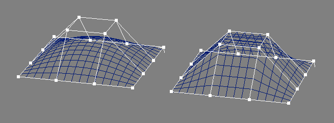
The PatchMesh object may be used to model with bicubic and bilinear patch meshes, see the image above for two examples.
Like NCurve objects, PatchMesh objects mark their last control point with a small arrow. Note that the arrow points in the V direction (height).
The following table briefly lists some capabilities of the PatchMesh object.
| Type | Parent of | Material | Converts to / Provides | Point Edit |
| PatchMesh | No | Yes | NPatch | Yes |
The first section of the PatchMeshAttr property contains patch specific settings:
"Type" may be set to "Bicubic" or "Bilinear"."Width" and "Height" control the dimensions of the patch.
Note that for bicubic patch meshes, the basis type may impose restrictions
on the valid values for width and height; e.g. for the
basis type "Bezier" (with step size 3) valid values are: 4, 7,
10, .... Another basis type that imposes this restriction is
"Hermite" (with step size 2), where valid values are: 4, 6,
8, ...."Bezier" is e.g. 6;
it is actually still 7, but the last point is equal to the first and
will be omitted.<Control> key is held down.[∗]
"Close_U" and "Close_V" determine, whether the patch
mesh should be closed in U and V direction respectively."IsRat" informs, whether the patch mesh
is rational (has any weight values different from
1.0).[∗]"BType_U" and "BType_V" control the basis type
for bicubic patches. The following basis types are available:
"Bezier", "B-Spline", "Catmull-Rom",
"Hermite", "Power", and "Custom".
In the latter case ("Custom"), additional parameters may be set.
Those are "Step_U"/"Step_V" (the step size of the basis) and
"Basis_U"/"Basis_V" the basis itself."Custom", the
initial values of the basis matrix will be of those of
the previous type.[∗]tobasisPM command,
see also section
tobasisPM command."BType_U", "BType_V", "Step_U",
"Step_V", "Basis_U", and "Basis_V" are
only available to bicubic patch meshes.
The next parameters control the appearance of the patch for display in Ayam:
"Tolerance" is in fact GLU sampling tolerance, used to
control the quality of the sampling when rendering the patch.
A setting of 0.0 means, that the global preference setting
"Drawing/Tolerance" should be used."DisplayMode" sets the display mode, either the control
hull is drawn, or just the outlines of the polygons created by
the tesselation (OutlinePolygon), or just the
outlines of the patch (OutlinePatch). The default setting
(Global) means, that the global preference setting
"Drawing/DisplayMode" should be used.The PatchMesh object supports the standard caps as lined out in section
Caps Property
and the standard bevels as lined out in section
Bevels Property
.[∗]
The boundary names are U0, U1, V0, and V1.
The patch mesh may be converted to an ordinary NURBS patch
using the main menu entry "Tools/Convert".
In Ayam versions prior to 1.21, conversion (and shaded display)
did not work for patch meshes with the basis types Catmull-Rom, Hermite,
or Custom. This is no longer the case.
PatchMesh objects will be exported as patch mesh primitives:
RiPatchMesh(...);
Multiple TC tags are also supported.[∗]
To create PatchMesh objects using the scripting interface see
section
crtOb PatchMesh command.
These objects create freeform surfaces from curves or other surfaces.

The Revolve object forms a surface of revolution from a NURBS curve, see the image above for an example.
The Revolve object has the generating NURBS curve as child object and watches its changes and adapts to it automagically.
The axis of revolution is always the Y-axis. The parameter curve should be defined in the XY-plane. If not, the curve will be projected to this plane before revolving.
The following table briefly lists some capabilities of the Revolve object.
| Type | Parent of | Material | Converts to / Provides | Point Edit |
| Revolve | NCurve / Trim+ | Yes | NPatch+ | No* |
The parameter "ThetaMax" specifies the
sweeping angle of the revolution just like for an ordinary
RenderMan quadric primitive.
The Revolve object also supports a B-Spline mode
that may be enabled by setting the parameter "Sections"
to a value higher than 0.[∗]
In this mode, a circular B-Spline is
used as basis for the surface of revolution instead of the
standard NURBS circle. Depending on the number of sections
chosen, the surface of revolution does not exactly interpolate
the parameter curve, but the surface may be edited more easily
after a possible conversion to an ordinary NURBS patch object,
because the control points will not be rational if the revolved
curve is also not rational.
Note that also the B-Spline mode can realize arbitrary
"ThetaMax" values.[∗]
In addition to the number of sections, in B-Spline mode it is
possible to control the order of the surface of revolution
using the parameter "Order". If "Order" is 0,
a standard value of 3 will be used.
See section
NPatchAttr for a description
of the other two attributes "DisplayMode" and "Tolerance".
The Revolve object supports the standard caps as lined out in section Caps Property and the standard bevels as lined out in section Bevels Property.
The boundary names are:
Upper – curve formed by revolving the start
point of the cross section,
Lower – curve formed by revolving the
end point of the cross section,
Start – cross section, and
End – cross section at end of revolution.
Revolve objects support direct trimming by Trim child objects as docmented in section Direct Trimming[∗].
The surface of revolution and the bevels and caps
may be converted to ordinary NURBS patches using the main menu entry
"Tools/Convert".
If bevels or caps are present, an enclosing Level object will be created and the bevels or caps follow the surface of revolution in the following order: upper, lower, start, end.
Integrated bevels or caps do not appear as extra objects.
The Revolve object provides a list of NURBS patch objects in the same order as created upon conversion.
Revolve objects will be exported as NURBS patch primitives:
RiNuPatch(...);
PV tags are supported.[∗]
Multiple TC tags are also supported.[∗]

The Extrude object forms a linear extrusion from a number of planar NURBS curves, see the image above for an example.
The first curve determines the outline and the other curves determine holes in the extrusion object. Holes may be used by objects that form e.g. letters.
The object has the generating NURBS curves as child objects, watches them and adapts to them automagically.
Consequently, the object hierarchy of an Extrude object may look like this:
+-Extrude
  |-Outline(NCurve)
  |-[Hole_1(NCurve)
  | ...
  \-Hole_n(NCurve)]
The Extrude object can generate caps, if the generating curves are closed. Cap generation may fail, if the outer curve has weights and the curve itself leaves the convex hull of the control polygon. Be careful when using curves with weights!
The sharp corners between caps and extrusion may be beveled.
The axis of the extrusion is always the Z-axis. The parameter curves should be defined in the XY-plane. If not, they will be squashed down to this plane. See section To XY Tool for information on how to easily achieve curves in the XY-plane.
The dimensions and orders of the extruded surface(s) will be taken from the respective parameter curves as follows: width and order in U direction will be 2, height and order in V direction are taken from the parameter curve.
The following table briefly lists some capabilities of the Extrude object.
| Type | Parent of | Material | Converts to / Provides | Point Edit |
| Extrude | NCurve+ / Trim+ | Yes | NPatch+ | No* |
The parameter "Height" determines how
big in Z direction the extrusion should be. Note that
the height of the bevels will not be taken into account here,
if the extrusion height is 1.0 and beveling (upper and lower) is
switched on with radius 0.1 the resulting object extends 1.2 units in
Z direction.
The Extrude object can automatically generate caps,
that are trimmed NURBS patches. Using "StartCap" and
"EndCap" you determine whether such caps should be generated,
default is off (no caps). Note that this feature does only work
properly, if the generating NURBS curves are closed and not self
intersecting, this is because the generating curves themselves are
used as trim curves for the caps. Warning, Ayam will not check whether
the parameter curves conform to these criteria. Ayam, however,
automatically detects the correct orientation of the curves (and
reverts them if necessary).
Since Ayam 1.10 the bevel parameters of the Extrude object are saved
in bevel parameter tags and the property GUI changed to conform to
all other bevel supporting tool objects. The old options "LowerBevel",
"UpperBevel", "BevelType", and "BevelRadius" are no
longer available. They were replaced with new dynamic tag creating
bevel property GUI sections that are accessible through the new
command entries "Add Start Bevel!" and "Add End Bevel!"
respectively. If one of those entries is used, a corresponding bevel
parameter tag is created and more options will be made available in the
property GUI to adjust the bevel parameters or remove the tag again.
A more thorough discussion of those options is available in
section
BevelAttr Property.
See section
NPatchAttr for a description
of the other two attributes "DisplayMode" and "Tolerance".
All curves forming holes in the extruded object must be defined inside (geometrically) the first curve (the outline curve). Additionally, they may not intersect each other or them self and there can not be hole curves inside hole curves. If there are bevels and caps, allow some extra spacing between the curves (for the bevels). Ayam will not check whether the parameter curves conform to these criteria.
With the direction of the curve, the direction of the bevel is determined as well (should it round outwards or inwards?). If the bevels of the holes look wrong try to revert the generating curves of the holes. Note that beveling does not work well with open curves. It is suggested to always use closed curves for beveling. Beveling may lead to self intersecting trim curves in sharp corners of an extrusion. Decrease the bevel radius or round the corners of the extruded curve (using insertion of additional control points) if cap generation fails due to self intersecting bevels.
Another special issue shall be noted: If there are holes, the corresponding bevels will be scaled with the hole curve object transformation values. Thus, to achieve equally sized bevels for outline and holes, possible scale transformations should be carried out on the hole curve control points, rather than on the hole curve object transformation attributes.
Extrude objects support direct trimming by Trim child objects as docmented in section Direct Trimming[∗].
The extruded surface, the bevels, and the caps
may be converted to ordinary NURBS patches using the main menu entry
"Tools/Convert".
If bevels or caps are present, an enclosing Level object will be created and the bevels and caps follow the extruded surface in the following order: end bevel, end cap, start bevel, start cap.
The Extrude object provides a list of NURBS patch objects in the same order as created upon conversion.
Extrude objects will be exported as NURBS patch primitives:
RiNuPatch(...);
PV tags are supported but all NURBS patch primitives will get the same set of tags.[∗]

The Swing object forms a surface that results from rotating a NURBS curve
(called cross section or profile) around an axis while
scaling it according to a second NURBS curve (called trajectory or
path).[∗]
This process is sometimes also called rotational sweep.
See the image above for an example.
The Swing object has the generating NURBS curves as child objects and watches their movements and adapts to them automagically. The first curve is the cross section, the second is the trajectory.
The object hierarchy of a Swing object, thus, looks like this:
+-Swing
  |-Cross_Section(NCurve)
  \-Trajectory(NCurve)
The swing operation will occur around the Y-axis, i.e. the trajectory should be defined in the XZ-plane.
The cross section curve should be defined in the YZ-plane and the trajectory should start here. See also the image below.
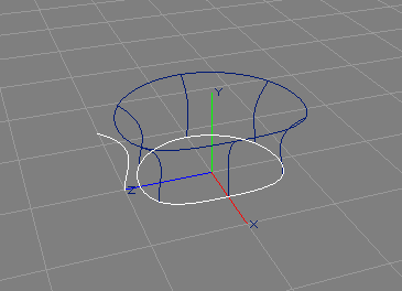
Note that the swing create tool will automatically modify the control points of NCurve, ICurve, and ACurve objects so that they are defined in the proper plane. For all other object types, the transformation attributes will be set (Rotate_Y is set to 90 if currently set to 0).[∗]
The dimensions and orders of the swung surface will be taken from the respective parameter curves as follows: width and order in U direction from the trajectory, height and order in V direction from the cross section.
The following table briefly lists some capabilities of the Swing object.
| Type | Parent of | Material | Converts to / Provides | Point Edit |
| Swing | NCurve∗ / Trim+ | Yes | NPatch+ | No* |
The swung surface is completely controlled by the parameter curves.
See section
NPatchAttr for a description
of the attributes "DisplayMode" and "Tolerance".
To help in the exact configuration of the swung surface, the "NPInfo"
field always displays the parameters of the created NURBS patch.
The Swing object supports the standard caps as lined out in section Caps Property and the standard bevels as lined out in section Bevels Property.
The boundary names are:
Start – cross section,
End – cross section at end of sweep,
Upper – curve formed by sweeping the start point of the
cross section, and
Lower – curve formed by sweeping the end point of the
cross section.
Swing objects support direct trimming by Trim child objects as docmented in section Direct Trimming[∗].
The swung surface and the caps
may be converted to ordinary NURBS patches using the main menu entry
"Tools/Convert".
If bevels or caps are present, an enclosing Level object will be created and the bevels or caps follow the swung surface in the following order: upper, lower, start, end.
Integrated bevels or caps do not appear as extra objects.
The Swing object provides a list of NURBS patch objects in the same order as created upon conversion.
Swing objects will be exported as NURBS patch primitives:
RiNuPatch(...);
PV tags are supported.[∗]
Multiple TC tags are also supported.[∗]

The Sweep object forms a surface that results from moving a NURBS curve (called cross section or profile) along a second NURBS curve (called trajectory or path). See the image above for an example.
The cross section may be scaled while sweeping using a third curve, the scaling function. Swept surfaces may be closed in the direction of the trajectory and they may also be periodic.[∗]
The Sweep object has the generating NURBS curves as child objects and watches their movements and adapts to them automagically. The first curve is the cross section, the second is the trajectory, and the third curve represents the scaling function.
The object hierarchy of a Sweep object, thus, looks like this:
+-Sweep
  |-Cross_Section(NCurve)
  |-Trajectory(NCurve)
  \-[Scaling_Function(NCurve)]
Note that the "Translate" attributes of the cross section curve
will be fully ignored. All other transformation attributes
(of cross section and trajectory) will be used to determine
place, orientation, and size of the Sweep object.
The cross section curve has to be defined in the YZ-plane of the
Sweep objects coordinate system. See also the image below.
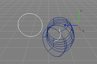
This means that a simple circular curve as e.g. created with the toolbox has to be rotated by 90 degrees around the Y-axis. This can be done either by modifying the control points, or by setting the transformation attributes accordingly. Later editing of this curve has to be done in a Side view. Note that the sweep create tool will automatically modify the control points of NCurve, ICurve, and ACurve objects so that they are defined in the proper plane. For all other object types, the transformation attributes will be set (Rotate_Y is set to 90 if currently set to 0).[∗]
The scaling function is sampled for each section and the Y-component of the coordinates of the current curve point will be used as scale factor that is applied to the cross section in Y-direction.
If any sample point of the scaling function has a Z-component different from zero, the Z-component will be used to independently scale the cross section in X-direction, otherwise the Y-component will be used to also scale the cross section in X-direction.[∗]
This implies, that e.g. a scaling function that does nothing should be a linear curve from (0,1,1) to (1,1,1). Scale components that are less than or equal to zero will be silently ignored.

Here is a short example for the creation of a sweep:
"Shift" key and select the other curve.)<e>,
then drag some control points around.)"Side". (Use the views "Type" menu or
the <PgDwn> keyboard shortcut while the view has the input focus.)Section Easy Sweep has an example script that automates creation and parameterisation of a suitable cross section curve.
Translational surfaces are a similar creation algorithm, see also section Translational Surface.
The following table briefly lists some capabilities of the Sweep object.
| Type | Parent of | Material | Converts to / Provides | Point Edit |
| Sweep | NCurve∗ / Trim+ | Yes | NPatch+ | No* |
The "Type" attribute controls whether the
swept surface should be open, closed, or periodic in the direction
of the trajectory curve.[∗]
If "Interpolation" is enabled, an additional interpolation
will be run on the swept surface in U direction so that all section
curves will be interpolated by the swept surface. Instead of a
NURBS knot vector, the swept surface will then get a
Chordal knot vector (calculated by knot averaging) and the
swept surface will follow the trajectory more closely.
See the image below for an example.
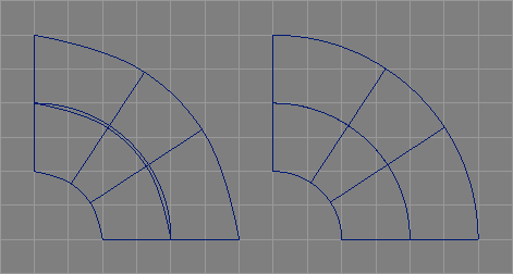
The third parameter, "Sections", determines how many
control points (in U direction) should be used, when generating the
sweep NURBS patch. The sweep NURBS patch has sections+1 control
points in U direction for open and closed sweeps, whereas
sections+order control points will be created for periodic sweeps.
Zero is a valid setting for the "Sections" parameter and used as
default value.[∗]
In this case the number of sections is directly derived from the length
of the trajectory curve plus one (except for trajectory curves of length
2, where the number of sections is 1).
For example, if "Sections" is zero, for a standard NURBS curve of
length 4, the number of sections used is 5 and the width of the created
NURBS patch is 6, for a curve with just 2 control points, the number of
sections used is 1 and the width of the resulting patch is 2.
See the table below for more examples.
Moreover, if "Sections" is zero, the order of the sweep in U direction
is taken from the trajectory curve. Otherwise, the order of the created
patch depends on the number of sections as follows: for 1 and 2 sections
the order will be 2 and 3 respectively, in all other cases it will be 4.
If "Rotate" is enabled, the cross sections will be
rotated so that they are always perpendicular to the trajectory,
this option is enabled by default.
See section
NPatchAttr for a description
of the other two attributes "DisplayMode" and "Tolerance".
To help in the exact configuration of the swept surface, the "NPInfo"
field always displays the parameters of the created NURBS patch.
The following table shows some example parameter configurations for the Sweep object.
| Sections | Trajectory Length | Trajectory Order | Sweep Length | Sweep Order |
| 0 | 2 | 2 | 2 | 2 |
| 0 | 5 | 4 | 6 | 4 |
| 0 | 6 | 5 | 7 | 5 |
| 4 | 6 | 5 | 5 | 4 |
| 10 | 6 | 5 | 11 | 4 |
The Sweep object supports the standard caps as lined out in section Caps Property and the standard bevels as lined out in section Bevels Property.
The boundary names are:
Start – cross section,
End – cross section at end of sweep,
Left – curve formed by sweeping the start point of the
cross section, and
Right – curve formed by sweeping the end point of the
cross section.
Sweep objects support direct trimming by Trim child objects as docmented in section Direct Trimming[∗].
The swept surface, the bevels and the caps
may be converted to ordinary NURBS patches using the main menu entry
"Tools/Convert".
If bevels or caps are present, an enclosing Level object will be created and the bevels and caps follow the swept surface in the following order: start bevel, start cap, end bevel, end cap, left bevel, left cap, right bevel, right cap.
Integrated bevels or caps do not appear as extra objects.
The Sweep object provides a list of NURBS patch objects in the same order as created upon conversion.
Sweep objects will be exported as NURBS patch primitives:
RiNuPatch(...);
PV tags are supported.[∗]
Multiple TC tags are also supported.[∗]
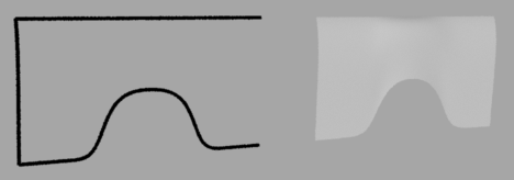
The Birail1 object forms a surface by sweeping a cross section (or profile) curve along two so called rail curves. See the image above for an example.
The object hierarchy of a Birail1 object, thus, looks like this:
+-Birail1
  |-Cross_Section(NCurve)
  |-Rail1(NCurve)
  \-Rail2(NCurve)
When the cross section touches the rail curves in their respective starting points, the resulting surface will interpolate the rail curves. The direction of the cross section curve will be parallel to the V parametric dimension (height) and the direction of the rail curves will be parallel to the U parametric dimension (width) of the resulting surface. Height and width of the surface will be derived from the length of the cross section curve and the number of sections, respectively.
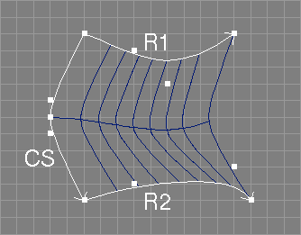
The image above shows a valid configuration of parameter curves for the Birail1 object. Mind the direction of the rail curves (R1 and R2) with regard to the cross section curve (CS) and the fact that the cross section curve touches the starting points of the rail curves.
Note that the cross section curve does not have to be two dimensional, and, in contrast to the normal Sweep object, it also does not have to be defined in a special plane. Also note that the precision with which the resulting surface will interpolate the rail curves depends on the number of sections chosen.
The Birail1 object watches the child objects and adapts to them automatically via the notification mechanism.
See also section DualSweep for a script object that creates a similar surface.
The following table briefly lists some capabilities of the Birail1 object.
| Type | Parent of | Material | Converts to / Provides | Point Edit |
| Birail1 | NCurve∗ / Trim+ | Yes | NPatch+ | No* |
The following parameters control the birailing process.
Similar to the Sweep object, the "Type" attribute controls whether the
birailed surface should be open, closed, or periodic in the direction
of the rail curves.
The parameter "Sections" determines how many
sections (in U direction) should be used, when generating the
birailed NURBS patch. The birailed NURBS patch always has sections+1 control
points in U direction.
Also zero is a valid setting for
the "Sections" parameter and used as default
value.[∗]
If "Sections" is zero the number of sections is directly derived from
the length of the first rail curve plus one (except for curves of length 2,
where it is 1). See the table below for examples.
Moreover, if "Sections" is zero, the order of the birail in U direction
is taken from the first rail curve. Otherwise, the order of the created
patch depends on the number of sections as follows: for 1 and 2 sections
the order will be 2 and 3 respectively, in all other cases it will be 4.
See section
NPatchAttr for a description
of the other two attributes "DisplayMode" and "Tolerance".
To help in the exact configuration of the birailed surface, the "NPInfo"
field always displays the parameters of the created NURBS patch.
The following table shows some example parameter configurations for the Birail1 object.
| Sections | Rail1 Length | Rail1 Order | Birail1 Length | Birail1 Order |
| 0 | 2 | 2 | 2 | 2 |
| 0 | 5 | 4 | 6 | 4 |
| 0 | 6 | 5 | 7 | 5 |
| 4 | 6 | 5 | 5 | 4 |
| 10 | 6 | 5 | 11 | 4 |
The Birail1 object supports the standard caps as lined out in section Caps Property and the standard bevels as lined out in section Bevels Property.
The boundary names are:
Start – cross section,
End – cross section at end of sweep,
Left – curve formed by sweeping the start point of the
cross section, and
Right – curve formed by sweeping the end point of the
cross section.
Birail1 objects support direct trimming by Trim child objects as docmented in section Direct Trimming[∗].
The birailed surface, the bevels, and the caps
may be converted to ordinary NURBS patches using the main menu entry
"Tools/Convert".
If bevels or caps are present, an enclosing Level object will be created and the bevels and caps follow the birailed surface in the following order: end bevel, end cap, start bevel, start cap, left bevel, left cap, right bevel, right cap.
Integrated bevels or caps do not appear as extra objects.
The Birail1 object provides a list of NURBS patch objects in the same order as created upon conversion.
Birail1 objects will be exported as NURBS patch primitives:
RiNuPatch(...);
PV tags are supported.[∗]
Multiple TC tags are also supported.[∗]
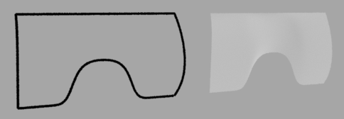
The Birail2 object forms a surface by sweeping a cross section (or profile) curve along two so called rail curves, while morphing it into a second cross section (or profile) curve. See also the image above for an example.
The morphing process may be controlled by a fifth parameter curve, the interpolation control curve. The object hierarchy of a Birail2 object, thus, looks like this:
+-Birail2
  |-Cross_Section1(NCurve)
  |-Rail1(NCurve)
  |-Rail2(NCurve)
  |-Cross_Section2(NCurve)
  \-[Interpolation_Control(NCurve)]
When the cross sections touch the rail curves in their respective starting or end points, the resulting surface will interpolate the rail curves. The direction of the cross section curves will be parallel to the V parametric dimension (height) and the direction of the rail curves will be parallel to the U parametric dimension (width) of the resulting surface. Height and width of the surface will be derived from the length of the cross section curves and the number of sections, respectively.

The image above shows a valid configuration of parameter curves for the Birail2 object. Mind the direction of the rail curves (R1 and R2) with regard to the two cross section curves (CS1 and CS2) and the fact, that all curves touch at their respective end points.
Note that the cross section curves do not have to be two dimensional, and, in contrast to the normal Sweep object, they also do not have to be defined in a special plane. Furthermore, they do not have to be compatible in terms of length, order, and knots. Incompatible curves will be made compatible before birailing automatically; the height of the resulting surface, however, is not easily predictable anymore in this case. Also note that the precision with which the resulting surface will interpolate the rail curves depends on the number of sections chosen.
If a fifth curve is present as parameter object, this curve will
control the morphing (interpolation) process. The y coordinate
of this curve at a specific point, which should have a value between
0 and 1, determines the ratio of control of the first cross section
(0) and the second cross section (1) over the interpolated curve.
Thus, a straight line running from point (0,0) to (1,1) will be equivalent
to the standard linear interpolation that would be carried out if no
interpolation control curve were present. Note, however, that the
interpolation control curve has no influence on the first and last
copy of the respective cross section curve, unless the "InterpolCtrl"
option is used.[∗]
The Birail2 object watches the child objects and adapts to them automatically via the notification mechanism.
The following table briefly lists some capabilities of the Birail2 object.
| Type | Parent of | Material | Converts to / Provides | Point Edit |
| Birail2 | NCurve∗ / Trim+ | Yes | NPatch+ | No* |
The following parameters control the birailing process.
The parameter "Sections" determines how many sections (in U direction)
should be used, when generating the birailed NURBS patch. The birailed
NURBS patch always has sections+1 control points in U direction.
Also zero is a valid setting for
the "Sections" parameter and used as default
value.[∗]
If "Sections" is zero the number of sections is directly derived from
the length of the first rail curve plus one (except for curves of length 2,
where it is 1). See the table below for examples.
Moreover, if "Sections" is zero, the order of the birail in U direction
is taken from the first rail curve. Otherwise, the order of the created
patch depends on the number of sections as follows: for 1 and 2 sections
the order will be 2 and 3 respectively, in all other cases it will be 4.
The parameter "InterpolCtrl" allows the interpolation controlling
curve full influence on the birailed surface.
If "InterpolCtrl" is disabled, the first and last border of the
resulting surface will always exactly match the parameter curves (CS1 and
CS2 respectively), regardless of the interpolation control curve.
See section
NPatchAttr for a description
of the other two attributes "DisplayMode" and "Tolerance".
To help in the exact configuration of the birailed surface, the "NPInfo"
field always displays the parameters of the created NURBS patch.
The following table shows some example parameter configurations for the Birail2 object.
| Sections | Rail1 Length | Rail1 Order | Birail2 Length | Birail2 Order |
| 0 | 2 | 2 | 2 | 2 |
| 0 | 5 | 4 | 6 | 4 |
| 0 | 6 | 5 | 7 | 5 |
| 4 | 6 | 5 | 5 | 4 |
| 10 | 6 | 5 | 11 | 4 |
The Birail2 object supports the standard caps as lined out in section Caps Property and the standard bevels as lined out in section Bevels Property.
The boundary names are:
Start – first cross section,
End – second cross section,
Left – curve formed by sweeping the start point of the
first cross section, and
Right – curve formed by sweeping the end
point of the first cross section.
Birail2 objects support direct trimming by Trim child objects as docmented in section Direct Trimming[∗].
The birailed surface, the bevels, and the caps
may be converted to ordinary NURBS patches using the main menu entry
"Tools/Convert".
If bevels or caps are present, an enclosing Level object will be created and the bevels and caps follow the birailed surface in the following order: end bevel, end cap, start bevel, start cap, left bevel, left cap, right bevel, right cap.
Integrated bevels or caps do not appear as extra objects.
The Birail2 object provides a list of NURBS patch objects in the same order as created upon conversion.
Birail2 objects will be exported as NURBS patch primitives:
RiNuPatch(...);
PV tags are supported.[∗]
Multiple TC tags are also supported.[∗]
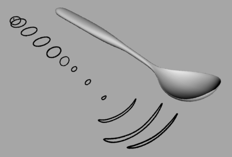
The Skin object forms a surface defined by a set of cross section curves, where the first and last curve will always be interpolated by the surface (this process is sometimes also called lofting). See also the image above.
When only two parameter curves are used, the skin forms a so called ruled surface.
The complete template for the Skin object hierarchy, consequently, looks like this:
+-Skin
  |-Curve_1(NCurve)
  |-Curve_2(NCurve)
  |-[...
  \-Curve_n(NCurve)]
Note that in contrast to the build from curves tool, the curves may be of arbitrary length and order. It is e.g. possible to use a parameter curve of order 2 and length 6 with a second curve of order 4 and length 4 and a third curve with order 3 and 5 control points. If the curves are of different length or order, they will all be converted internally until they are compatible. Be warned, that this process may consume a considerable amount of time because all unclamped curves have to be converted to clamped ones; then, for every curve with low order degree elevation has to be done; then a uniform knot vector has to be found; then all curves have to be refined using this new knot vector; interpolation adds another dimension of complexity. If you experience lags when editing the child curves of a Skin object try to switch to lazy notification.
A Skin object will also use all the curves of a tool object, that provides multiple curves, e.g. a Clone object in mirror mode.[∗]
The direction of the parameter curves will be parallel to the V dimension (height) of the skinned surface. The number of the parameter curves will define the U dimension (width) of the skinned surface.
Also note that the resulting patch may be quite complex, even though the curves are not, if the orders or knot vectors of the curves do not match. For example, a skinned patch from two curves of length 4 but one with order 4 and the other with order 2 will result in a patch with a width of 2 and a height of 10.
The Skin object has the generating NURBS curves as child objects and watches their changes and adapts to them automagically.
The following table briefly lists some capabilities of the Skin object.
| Type | Parent of | Material | Converts to / Provides | Point Edit |
| Skin | NCurve∗ / Trim+ | Yes | NPatch+ | No* |
The following parameters control the skinning process.
The first parameter "Interpolation" controls
whether the inner curves should also be interpolated by the
skinning surface.
The second parameter "Order_U" determines the order
of the resulting surface in U direction (the order in V direction is
determined by the curves). The order may not be higher than the
number of curves used. If the specified value is higher than the number
of curves, the order of the generated surface will be silently
set to the number of curves.
If "Order_U" is 0, a default value equal to the number of parameter
curves but not higher than 4 will be used.
Using the next parameter "Knot-Type_U", the type of the knot vector
that should be used in the U direction of the skinned surface can be
adapted. If the knot type is "Bezier" and the specified
order (see above) does not exactly match the number of skinned curves,
then the order will be silently adapted to the number of skinned curves.
The knot type "Custom" creates a chord length
parameterisation.[∗]
If interpolation is enabled, the knot types "Chordal",
"Centripetal", and "Uniform" will be used in the interpolation,
all other types will lead to a chordal parameterisation of the
interpolation.[∗]
See section
NPatchAttr for a description
of the other two attributes "DisplayMode" and "Tolerance".
To help in the exact configuration of the skinned surface, the "NPInfo"
field always displays the parameters of the created NURBS patch.
The Skin object supports the standard caps as lined out in section Caps Property and the standard bevels as lined out in section Bevels Property.
The boundary names are:
Start – first parameter curve,
End – last parameter curve,
Left – curve through start points of parameter curves, and
Right – curve through end points of parameter curves.
Skin objects support direct trimming by Trim child objects as docmented in section Direct Trimming[∗].
The skinned surface, the bevels, and the caps
may be converted to ordinary NURBS patches using the main menu entry
"Tools/Convert".
If bevels or caps are present, an enclosing Level object will be created and the bevels and caps follow the skinned surface in the following order: start bevel, start cap, end bevel, end cap, left bevel, left cap, right bevel, right cap.
Integrated bevels or caps do not appear as extra objects.
The Skin object provides a list of NURBS patch objects in the same order as created upon conversion.
Skin objects will be exported as NURBS patch primitives:
RiNuPatch(...);
PV tags are supported.[∗]
Multiple TC tags are also supported.[∗]

The Gordon object forms a surface defined by two sets of intersecting curves (a network of curves), where all curves will always be interpolated by the surface (see image above). The image below shows the simplest configuration of such a network, consisting of four parameter curves. Note the arrangement and the direction of the curves. Also note that this configuration is in fact equivalent to a Coons patch.

The curves may be of arbitrary length and order. It is e.g. possible to use a first curve of order 2 and length 6 with a second curve of order 4 and length 4 and a third curve with order 3 and 5 control points for the U parametric dimension.
Note that all intersection points of a curve with other curves have to have the same parametric value in each of the other curves in the same set/direction. All curves are so called isoparametric curves.
Also note, that in the general case only non-rational curves can be used as parameter curves for a Gordon surface. If the parameter curves are rational, the weight information of the curves will simply be ignored. However, since Ayam 1.13 there is a special case allowed: if exactly four parameter curves are present, their weight information will be used properly. Mind that for a correct surface interpolation the curves weights have to match in the respective end points.
The Gordon object has the generating NURBS curves as child objects and watches their changes and adapts to them automagically. Separation of the two sets of curves has to be done using an empty Level object. The first set of curves determines the U direction and the second set of curves the V direction of the Gordon surface. For the example surface in the image above, the child objects of the Gordon object would have to look like this in the Ayam object tree view:
+-Gordon
  |-U1(NCurve)
  |-U2(NCurve)
  |-Level
  |-V1(NCurve)
  \-V2(NCurve)
The creation of a Gordon surface is computationally expensive. It involves (interpolated) skinning of the two sets of parameter curves, finding the intersection points of the two sets of parameter curves, interpolating the matrix of intersection points, making the three resulting surfaces compatible, and finally combining the three surfaces into the resulting Gordon surface. If there are lags while editing the parameter curves of a Gordon surface, consider switching to lazy notification.
In order to ease the computationally intensive intersection
detection for Ayam an additional parameter object, separated
from the two sets of parameter curves by a second empty Level object,
may be specified.
This parameter object should be a NURBS patch object that describes
all intersection points by its control points.
If this object is present, no intersection points will be calculated
internally and the points specified via this object will be used instead.
A "NoExport" tag should be added to this patch, to prevent
it from appearing in RIB output.
The object hierarchy of a Gordon object using such a patch may look like this:
+-Gordon
  |-U1(NCurve)
  |-U2(NCurve)
  |-Level
  |-V1(NCurve)
  |-V2(NCurve)
  |-Level
  \-Intersections(NPatch)
The complete template for the Gordon object hierarchy, consequently, is as follows:
+-Gordon
  |-U1(NCurve)
  |-U2(NCurve)
  |-[...
  |-Un(NCurve)]
  |-Level
  |-V1(NCurve)
  |-V2(NCurve)
  |-[...
  |-Vn(NCurve)]
  |-[Level
  \-Intersections(NPatch)]
The Gordon object watches the child objects and adapts to them automatically via the notification mechanism.
The following table briefly lists some capabilities of the Gordon object.
| Type | Parent of | Material | Converts to / Provides | Point Edit |
| Gordon | NCurve∗/ Level / NPatch / Trim+ | Yes | NPatch+ | No* |
The following parameters of the Gordon object control the creation of the Gordon surface.
If the parameter "WatchCorners" is switched on, Ayam will
check for all four outer parameter curves, whether they touch in their
endpoints. If not, the endpoints will be corrected. If Ayam can
determine which curve was modified last, the other curve that should
meet at the endpoint in question will be modified.
If Ayam finds no information on modifications, the U curves take
precedence (i.e. the V curves will be modified).
Note that this works only properly with clamped curves.
Furthermore, only NCurve, ICurve, or ACurve objects will be modified,
but end point data will be derived from any objects providing a
NCurve (e.g. ExtrNC).[∗]
The parameters "Order_U" and "Order_V" determine the
desired order of the resulting surface in U and V direction.
However, depending on the number and configuration of curves used
in the U or V direction, it may not be possible to create a Gordon
surface of the desired order.
If "Order_U" or "Order_V" are 0, a default value
of 4 will be used.
See section
NPatchAttr for a description
of the other two attributes "DisplayMode" and "Tolerance".
To help in the exact configuration of the Gordon surface, the "NPInfo"
field always displays the parameters of the created NURBS patch.
The Gordon object supports the standard caps as lined out in section Caps Property and the standard bevels as lined out in section Bevels Property.
The boundary names are:
U0 – first curve of first set,
U1 – last curve of first set,
V0 – first curve of second set, and
V1 – last curve of second set.
Gordon objects support direct trimming by Trim child objects as docmented in section Direct Trimming[∗].
The Gordon surface, the bevels, and the caps may be converted to
ordinary NURBS patches using the
main menu entry "Tools/Convert".
If bevels or caps are present, an enclosing Level object will be created and the bevels and caps follow the Gordon surface in the following order: u0 bevel, u0 cap, u1 bevel, u1 cap, v0 bevel, v0 cap, v1 bevel, v1 cap.
Integrated bevels or caps do not appear as extra objects.
The Gordon object provides a list of NURBS patch objects in the same order as created upon conversion.
Gordon objects will be exported as NURBS patch primitives:
RiNuPatch(...);
PV tags are supported.[∗]
Multiple TC tags are also supported.[∗]
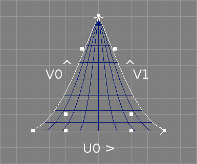
Apart from the Coons patch mode, Gordon objects also support another
special mode where a triangular surface is formed from three parameter
curves.[∗]
See also the image above. In this mode the three parameter curves do not have
to be separated by a Level object. The created NURBS surface is degenerate
at v = 1.0, however, a special tesselation is used for shading these
surfaces so that no artefacts should be visible.
This tesselation can also be accessed using the scripting interface
command "convOb PolyMesh".
As they are a special case of Coons patches, triangular Gordon surfaces
also support rational coordinates.
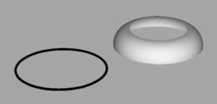
The Bevel object forms a bevelled surface from a single parameter curve. See also the image above. The bevel cross section shape may be defined by a second curve. Consequently, the template for the object hierarchy of a Bevel object looks like this:
+-Bevel
  |-NCurve
  \-[NCurve]
Bevels are also available as properties of different tool objects (e.g. Extrude or Sweep). In fact, Bevel objects use the same creation algorithm as bevel properties but offer increased flexibility in terms of e.g. material settings. Surfaces created from bevel properties always share the material settings of the progenitor tool object. In contrast, Bevel objects may have their own material settings. Bevel objects are available in Ayam since version 1.10.
Note that the parameter curve of a Bevel object should be closed and planar to achieve best results; see section To XY Tool for information on how to easily achieve this. If the curve is closed or periodic, the appropriate curve type should be set in the curve object, otherwise the bevelled surface may expose defects.
Since Ayam 1.19 the Bevel object supports a second parameter curve that defines the bevels cross section shape. It should be defined in the XY-plane and run from (0, 0) to (1, 1). If this curve is present, the Bevel type parameter is ignored as the shape of the bevel is already completely defined. Note that even though the curve should end at (1, 1), this is not mandatory and therefore allows for bevels of differing width and height to be created.
The Bevel object watches the child object and adapts to it automatically via the notification mechanism.
The following table briefly lists some capabilities of the Bevel object.
| Type | Parent of | Material | Converts to / Provides | Point Edit |
| Bevel | NCurve+ / Trim+ | Yes | NPatch | No* |
The following parameters of the Bevel object control the creation of the bevelled surface:
"BevelType" determines the shape of the bevel by choosing
from a set of cross section curves:
"Round" a quarter circle,
"Linear" a straight bevel,
"Ridge" a more complex ridged surface,
"RoundToCap" a surface that starts in the direction of a
progenitor surface tangent and rounds off to a cap surface (tangents
must be present as tag on the parameter curve), this types provides a
smoother transition from the progenitor surface to the bevel than a
round bevel, see also the image below,
"RoundToNormal" a surface that starts in the direction of a
progenitor surface tangent and rounds off to a mean normal,
see also the image below, normals and tangents must be present as tag
on the parameter curve, the mean normal can also be provided by a MN tag,
see section
MN (Mean Normal) Tag,
"Bevels"
also appear as potential bevel type. Those curves should follow
the rules laid out above for the second parameter curve of the
Bevel object.

Note that the bevel types "RoundCapped" and "LinearCapped"
are no longer available[∗],
use the "Caps" property to create caps.
"Radius" controls the size and direction of the bevelled
surface when seen from the top of the parameter curve. Note that the
size of the bevel is expressed in units defined by the object coordinate
system of the controlling object. Scale values of the controlling object
also affect the bevel size. Negative values are allowed and reverse the
surface.
"Revert" allows to revert the sense of the bevelled surface,
should it round inwards or outwards? The sense may also be controlled
using the direction of the parameter curve and, additionally, the sense
in a different dimension may also be affected by using negative values
for the bevel radius.
"Force3D" switches to 3D mode for all bevel types; if this
is enabled, non-planar parameter curves are supported, but normals
and tangents must be present as PV tag on the parameter curve.
However, when bevels are created via the Bevels property, the normals and
tangents will be extracted from the progenitor surface automatically and no
PV tags need to be created.To create the tag with the normal and tangent information,
the "Extract" option of the ExtrNC object can be used.
Otherwise PV tags of appropriate name, storage class, and data type
must be created manually or with the help of the scripting interface.
Consider the following example script:
crtOb NCurve -length 4 -order 2 -cv {0 0 0 1  1 0 0 1  0 1 0 1  0 0 0 1}
uS;sL
addTag PV "N,varying,n,4, -1,0,0, 1,0,0, 0,1,0, -1,0,0"
addTag PV "T,varying,n,4, 0,0,1, 0,0,1, 0,0,1, 0,0,1"
Also note that the planarity and exact shape defined by rational
coordinate values (e.g. circular arcs) will not be preserved by
the bevel types that support non-planar curves with one exception:
RoundToCap bevels on fully planar curves/boundaries do preserve
the boundary shape fully (unless overridden by
"Force3D").[∗]
See section
NPatchAttr for a description
of the two attributes "DisplayMode" and "Tolerance"
of the "BevelAttr" property.
To help in the exact configuration of the bevel surface, the "NPInfo"
field always displays the parameters of the created NURBS patch.
The Bevel object supports the standard caps as lined out in section Caps Property.
The boundary names are:
Start – start of bevel cross section,
End – end of bevel cross section.
Bevel objects support direct trimming by Trim child objects as docmented in section Direct Trimming[∗].
The bevelled surface may be converted to an ordinary NURBS patch using the
main menu entry "Tools/Convert".
If caps are present, an enclosing Level object will be created and the caps follow the bevel surface in the following order: start cap, end cap.
Bevel objects will be exported as NURBS patch primitives:
RiNuPatch(...);
If caps are present, those follow as potentially trimmed NURBS patch primitives in the following order: start cap, end cap.
PV tags are supported.[∗]
Multiple TC tags are also supported.[∗]

The Cap object forms a surface that fills a closed NURBS curve. See also the image above.
Four different types of cap surfaces with different characteristics and parameter curve requirements are supported: Trim, Gordon, Simple, and Simple3D.[∗]
The Trim cap type requires planar parameter curves but they may be concave. Furthermore, if multiple curves are present as child objects, the curves following the first curve define holes in the cap surface, similar to the parameter curves of an extruded surface (see also section Using Holes and Bevels).
Consequently, the template for the object hierarchy of a Cap object in Trim mode looks like this:
+-Cap
  |-Outline(NCurve)
  |-[Hole1(NCurve)]
  +-[Hole2(Level)
    |-Part1(NCurve)
    \-Part2(NCurve)]
Note that the cap generation may fail, if the control points of the first curve have weights and the curve leaves the convex hull of the control polygon.
The Gordon cap type supports only a single parameter curve but this curve may be non planar. Internally the Cap object will split the parameter curve into four sections and build a Gordon surface from the four sections (see the following image for an example).
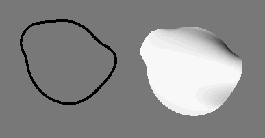
The Simple cap type just extends the parameter curve linearly to a middle point, not supporting non planar curves well and not supporting concave curves at all but ensuring compatibility with the progenitor curve/surface (which may be important for tesselation or further surface processing).
The Simple3D cap type extends the parameter curve to a middle point via an additional planar and circular ring of control points, therefore rounding more smoothly to the middle (especially useful for non planar parameter curves or parameter curves with discontinuities), and retains all other characteristics of the Simple type.
A MP tag can be set to the Cap object to control the middle point in both simple modes (see section MP (Mean Point) Tag).
See also the following table for an overview on the available cap types:
| Type | Planar | Concave | Holes | Compatibility / Integration |
| Trim | Yes | Yes | Yes | No |
| Gordon | No | No | No | No |
| Simple | Yes | No | No | Yes |
| Simple3D | No | No | No | Yes |
The Cap object watches the child objects and adapts to them automatically via the notification mechanism.
The following table briefly lists some capabilities of the Cap object.
| Type | Parent of | Material | Converts to / Provides | Point Edit |
| Cap | NCurve+ / Trim+ | Yes | NPatch | No* |
The following parameters control the cap creation process.
The attribute "Type" allows to select one of the following
cap creation methods:
"Trim": a trimmed NURBS surface,"Gordon": an untrimmed Gordon surface,"Simple": a simple cap that extends linearly to a middle
point,"Simple3D": a simple cap with an additional ring of control
points that therefore rounds more smoothly to the middle especially for
non planar parameter curves.The "Fraction" parameter allows to adjust the placement of the
additional control point ring in Simple3D mode.
See section
NPatchAttr for a description
of the two attributes "DisplayMode" and "Tolerance"
of the "CapAttr" property.
To help in the exact configuration of the cap surface, the "NPInfo"
field always displays the parameters of the created NURBS patch.
Cap objects support direct trimming by Trim child objects as docmented in section Direct Trimming[∗].
The cap surface may be converted to an ordinary NURBS patch using the
main menu entry "Tools/Convert".
Cap objects will be exported as NURBS patch primitives:
RiNuPatch(...);
PV tags are supported.[∗]
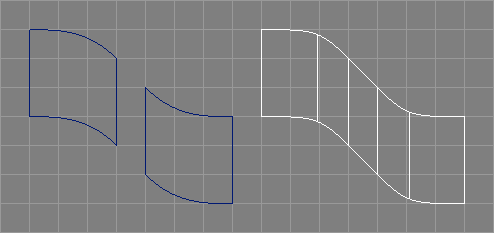
The ConcatNP object concatenates all child objects, which should be NURBS patches or provide NURBS patches to a single NURBS patch (see also the image above).[∗]
The concatenation simply breaks all surfaces into curves, makes the curves compatible, and joins them to the concatenated surface.
Also NURBS curves or objects that provide NURBS curves can be used as parameter objects.[∗]
Eventually present trim curves will be copied and transformed to the appropriate place and orientation in the concatenated surface, according to the new knot domain.[∗]
Attributes like display mode and tolerance for the new concatenated patch are simply taken from the first parameter patch.
Since the ConcatNP object also provides a NURBS patch, it is possible to use it as child object for another ConcatNP object (with possibly different parameters). This way, a hierarchy of ConcatNP objects can be used to emulate patch based modelling to certain extents.
For best results, only clamped surfaces should be used as parameter objects.
The following table briefly lists some capabilities of the ConcatNP object.
| Type | Parent of | Material | Converts to / Provides | Point Edit |
| ConcatNP | NPatch∗/ NCurve∗ / Trim+ | Yes | NPatch+ | No* |
The following parameters control the concatenation process.
"Type", open, closed, or periodic concatenated patches may
be created.
If a closed surface is to be created and also "FillGaps" (see below) is
enabled, an additional fillet will be created for the last and the first
child surface to close the concatenated surface.
"Order" is the desired order of the concatenated surface
(in U direction), the default value (0) leads to a cubic surface.
If the desired order is 1, the respective order from the first
of the parameter surfaces is taken.
If the desired order is higher than the number of curves (i.e. the
total number of control points of all surfaces in their desired
directions plus the number of eventually present parameter curves),
it will be lowered to the number of curves silently.
"FillGaps" creates fillet surfaces for all gaps between
the parameter surfaces of the ConcatNP object. No fillet will be created
if the end curves of two parameter surfaces match or if parameter
curves are present between the parameter surfaces in question.
Similar to the fillets for concatenated curves, the fillet surface will be constructed from four control points (in U direction). However, the tangent vectors will not be calculated directly, but instead derived from the respective control points.
"FTLength" determines the distance of the inner fillet
control points from their respective end points. This value can
be adapted for smaller/larger gaps between parameter
surfaces. If this parameter is negative, the distance between the
two surfaces in the respective border points will be multiplied in so
that a more pleasing fillet shape results in configurations where the
distances between the respective border points vary a lot (see also the
image below).
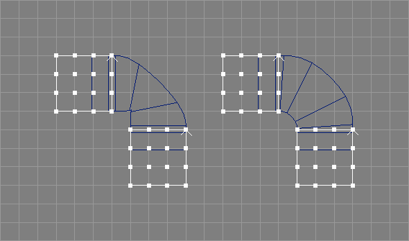
"Revert" is enabled, the orientation of the concatenated
surface will be reversed (in U direction).
"Knot-Type" parameter allows to choose a knot vector for
the concatenated surface in U direction. Similar to the
ConcatNC object, only "Custom" knots allow to preserve the shapes
of the parameter surfaces completely, but this comes at the price of multiple
internal knots (see also
ConcatNCAttr Property).
In addition, for "Custom" knots, all parameter surfaces will be
elevated to a common maximum order or at least be clamped in the
respective direction prior to the splitting to curves but after
the fillet creation. Furthermore trim curves of the progenitor surfaces
will only be copied to the resulting surface, if the "Knot-Type"
parameter is "Custom".
"UVSelect" option is a string that can be used to
control the splitting direction for each parameter surface
individually. Valid characters in this string are "u", "U",
"v", and "V".
The uppercase variants lead to a reverted surface in the respective
direction."UVSelect" should be set to "uV"
(see also the image below)."UVSelect", an empty string, is equivalent
to "u" for all patches. Also incomplete strings will lead to "u"
for all remaining patches. There is no need to specify a value for fillets,
those will always be created in a way so that they can be split along the
U direction.
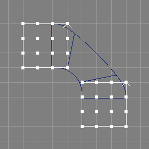
"Compatible" controls whether the curves should be
made compatible before the concatenated surface is built from
them. If this option is turned off (the default), the curves
are made compatible. Turn this option on if the surfaces to be
concatenated are already compatible and their knot vectors are unclamped.
The output surface will then also be unclamped (in V direction).
"NPInfo" field informs about the actual configuration
of the created NURBS patch.The ConcatNP object supports the standard caps as lined out in section
Caps Property
and the standard bevels as lined out in section
Bevels Property.
The boundary names are U0, U1, V0, and V1.
ConcatNP objects support direct trimming by Trim child objects as docmented in section Direct Trimming[∗].
The concatenated surface may be converted to an ordinary NURBS patch using the
main menu entry "Tools/Convert".
If bevels or caps are present, an enclosing Level object will be created and the bevels and caps follow the concatenated surface in the following order: U0 bevel, U0 cap, U1 bevel, U1 cap, V0 bevel, V0 cap, V1 bevel, V1 cap.
Integrated bevels or caps do not appear as extra objects.
The ConcatNP object provides a list of NURBS patch objects in the same order as created upon conversion.
ConcatNP objects will be exported as NURBS patch primitives:
RiNuPatch(...);
PV tags are supported but all NURBS patch primitives will get the same set of tags.[∗]
Multiple TC tags are also supported.[∗]
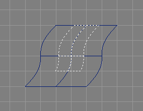
The ExtrNP object extracts a NURBS patch from another NURBS patch object, for use as parameter object for other tool objects (see image above).[∗]
It also works with NURBS patch providing objects, so that the following example hierarchy is valid:
--NPatch
+-ExtrNP
 \ Instance_of_NPatch(Instance)
"Tools/Create/ExtrNP"
will automatically create an instance of the currently selected object
and move it to the newly created ExtrNP object.
As the geometry of the extracted surface is completely defined by the master surface, ExtrNP objects do not support own transformation attributes.[∗] However, if a NP tag makes the Transformation property available again, the transformation attributes will be employed as usual.[∗]
Also note that eventually present trim curves will not be honored properly.
The following table briefly lists some capabilities of the ExtrNP object.
| Type | Parent of | Material | Converts to / Provides | Point Edit |
| ExtrNP | NPatch | Yes | NPatch+ | No* |
The extraction process is controlled by the following attributes:
"UMin", "UMax", "VMin", and "VMax" are
parametric values that control which part of the original surface
is to be extracted. The valid range of parameter values depends
on the knot vectors of the original surface.
"Relative" controls whether the parametric values should
be interpreted in a relative way.[∗]
If enabled, a parametric value of 0.5
always extracts from the middle of the knot vector, regardless of the
actual knot values, and the valid range for the parametric values is
then consequently 0.0-1.0.
"PatchNum" allows to select a patch from a list of
patches delivered e.g. by a beveled Extrude object as child
of the ExtrNP object.
This way it is possible to extract a patch from a bevel or cap
surface of e.g. a Revolve object.
"DisplayMode" and "Tolerance"."NPInfo" field informs about the actual configuration
of the extracted NURBS surface.The ExtrNP object supports the standard caps as lined out in section
Caps Property
and the standard bevels as lined out in section
Bevels Property.
The boundary names are U0, U1, V0, and V1.
The extracted surface may be converted to an ordinary NURBS patch using the
main menu entry "Tools/Convert".
If bevels or caps are present, an enclosing Level object will be created and the bevels or caps follow the extracted surface in the following order: U0, U1, V0, V1.
Integrated bevels or caps do not appear as extra objects.
The ExtrNP object provides a list of NURBS patch objects in the same order as created upon conversion.
ExtrNP objects will be exported as NURBS patch primitives:
RiNuPatch(...);
PV tags are supported but all NURBS patch primitives will get the same set of tags.[∗]
Multiple TC tags are also supported.[∗]
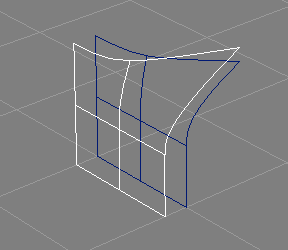
The OffsetNP object creates offset surfaces from NURBS surfaces using a simple algorithm: each control point is moved along a normal vector obtained by all direct neighboring control points.[∗] See also the image above.
The offset surface will always match the original surface in width, height, orders, and knots.
The offsetting also works for closed and periodic surfaces in any possible combinations in the two dimensions.[∗] Degenerate surfaces are supported.[∗] However note that rational surfaces are still not supported. No attempt is made to prevent collisions or self intersections.
Trim curves are copied verbatim from the parameter surface to the offset surface.
As the geometry of the offset surface is completely defined by the master surface and the offset parameter, OffsetNP objects do not support own transformation attributes.[∗]
The following table briefly lists some capabilities of the OffsetNP object.
| Type | Parent of | Material | Converts to / Provides | Point Edit |
| OffsetNP | NPatch | Yes | NPatch+ | No* |
The following parameters control the offsetting process:
"Offset" determines the distance between original surface and
offset surface. Negative values are allowed.
"DisplayMode" and "Tolerance"."NPInfo" field informs about the actual configuration
of the created NURBS surface.The OffsetNP object supports the standard caps as lined out in section
Caps Property
and the standard bevels as lined out in section
Bevels Property.
The boundary names are U0, U1, V0, and V1.
The offset surface may be converted to an ordinary NURBS patch using the
main menu entry "Tools/Convert".
If bevels or caps are present, an enclosing Level object will be created and the bevels or caps follow the offset surface in the following order: U0, U1, V0, V1.
Integrated bevels or caps do not appear as extra objects.
The OffsetNP object provides a list of NURBS patch objects in the same order as created upon conversion.
OffsetNP objects will be exported as NURBS patch primitives:
RiNuPatch(...);
PV tags are supported but all NURBS patch primitives will get the same set of tags.[∗]
Multiple TC tags are also supported.[∗]

Text objects may be used to easily create objects that form letters or even whole words in very high quality. For that, they parse TrueType font description files, extract the Bezier curves from the font description, sort the curves, connect them properly and finally extrude them. As with the Extrude objects, caps and bevels may be created automatically.
Parsing of TrueType font descriptions is quite tricky. For the sake of brevity and ease of the implementation, Ayam does not support elaborate TrueType features like kerning tables, that e.g. control distances between certain letters (You are not going to typeset a book with Ayam anyway, aren't you?). Therefore you might experience wrong letter distances from time to time. If this happens, just create a Text object for each letter, and arrange the objects as you like.
The Text object can be converted to ordinary NURBS patches
using the main menu entry "Tools/Convert".
The following table briefly lists some capabilities of the Text object.
| Type | Parent of | Material | Converts to / Provides | Point Edit |
| Text | No | Yes | NPatch+ | No* |
The following attributes control the creation of the text objects.
"FontName" a TrueType font description file is
specified.
Those files usually have the file name extension ".ttf".
Only real TrueType font files, containing Bezier curve font descriptions,
are supported. There are also rastered, bitmap containing TrueType
font description files, those will not work.
"String" you specify the letters to be created.
This entry (and the corresponding data structures) are Unicode clean.
This means you can put any Unicode letters into this entry. You should
of course make sure, that the specified letters are included in the
selected font file.
"Height" controls the height of the extruded object.
"Revert" reverts the sense of inside-outside detection
mechanism for the cap generation. Depending on the actual font description
file (or even letter) you may need to toggle this to get caps.
"UpperCap", "LowerCap", work like for the Extrude object
(see section
ExtrudeAttr Property for a more
exhaustive description of those parameters).
"Add Lower Bevel!", "Add Upper Bevel!":
Since Ayam 1.10 the bevel parameters of the text object are saved
in bevel parameter tags and the property GUI changed to conform to
all other bevel supporting tool objects. The old options "LowerBevel",
"UpperBevel", "BevelType", "BevelRadius", and
"RevertBevels" are no longer available. They were replaced with
new dynamic tag creating bevel property GUI sections that are accessible
through the new command entries "Add Lower Bevel!" and
"Add Upper Bevel!"
respectively. If one of those entries is used, a bevel parameter tag
is created and more options will be made available in the property
GUI to adjust the bevel parameters or remove the tag again.
A more thorough discussion of those options is available in
section
BevelAttr Property.
Just one note: for some fonts, the bevel radius has to be set to really small values (about 0.001) to get proper bevels and caps. This is because of sharp corners in some letters that lead to self overlapping borders of the bevel surfaces with otherwise perfectly normal values for the bevel radius.
See section
NPatchAttr for a description
of the other two attributes "DisplayMode" and "Tolerance".
The extruded surfaces, the bevels, and the caps,
may be converted to ordinary NURBS patches using the main menu entry
"Tools/Convert".
If bevels or caps are present, an enclosing Level object will be created and the caps follow the extruded surfaced in the following order: end bevel, end cap, start bevel, start cap.
The Text object provides a list of NURBS patch objects in the same order as created upon conversion.
Text objects will be exported as NURBS patch primitives:
RiNuPatch(...);
PV tags are supported but all NURBS patch primitives will get the same set of tags.[∗]
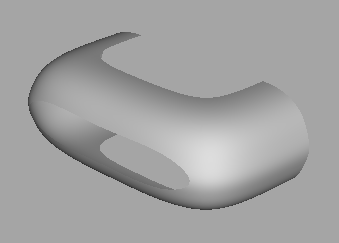
The Trim object may be used in hierarchies of tool objects to trim NURBS patch providing objects otherwise unavailable to trimming like e.g. a Revolve object.[∗]
See also the image above which depicts the swung surface example object further trimmed by a Trim object.
The first child of the Trim object is the NURBS patch providing object and the second object is the trim curve (defined in the parametric space of the NURBS surface). More curves and loops may follow. All parameter curves must obey the rules for trimming as outlined in section Trim Curves. The surface may already be trimmed and there may be multiple provided patches, however, only one of them will be trimmed by the Trim object.
The object hierarchy of a Trim object, thus, looks like this:
+-Trim
  |-Surface(Revolve)
  |-Trim_1(NCurve)
  +-[Trim_2(Level)
  | |-NCurve
  | \-NCurve
  | ...
  \-Trim_n(ICurve)]
The following table briefly lists some capabilities of the Trim object.
| Type | Parent of | Material | Converts to / Provides | Point Edit |
| Trim | NPatch / NCurve+/ Level+ | Yes | NPatch | No |
The following parameters control the trimming process:
"PatchNum" allows to select a patch, should the NURBS
patch providing object deliver a list. This way, a bevel of an
extrusion might be trimmed."ScaleMode" controls how the trim curve is scaled
to the NURBS patch parameter space:"Absolute" no scaling happens."Relative" the trim curves are expected to be defined
between 0 and 1 (in x and y dimension) and
will be scaled to the patch appropriately, no matter how the
parametric space of the patch actually looks like (i.e. it works
the same for a patch where the knots range from 0 to 1, 0 to 2,
or even 3 to 3.5)."3D" the curve is to specified in 3D space near the
surface and will be projected to the parametric space of the NURBS
patch.[∗]
PP tags can be used to adjust the projection, see also
section
PP tag.The trimmed surface may be converted to an ordinary NURBS patch
using the main menu entry "Tools/Convert".
Trim objects will be exported as NURBS patch primitives:
RiNuPatch(...);
Several surface creating tool objects support Trim objects as
child objects, this is
called direct trimming.[∗]
For instance, consider the following example hierarchy:
+-Revolve
  |-Cross_Section(NCurve)
  +-Trim
    \-Trim_Curve(NCurve)
Note, that in contrast to normal use, the Trim object has no surface as
child but only a curve, i.e. it does not create/modify a surface on its
own but rather serves as an indicator for the Revolve object, that trim
curves are present.
Direct trimming means, that, after the creation of the respective NURBS
surface, the trim curves provided by the Trim child object(s) will be
added to the created NURBS patch object (in the example above, to the
surface of revolution).
If multiple surfaces are created, the "PatchNum" attribute of the
Trim object can be used to specify the surface to trim.
However, note that the creation of caps and/or bevels of the respective
tool object is completely oblivious of the trimming.
These objects complement the Ayam feature set and allow objects modelled in the polygonal or subdivision modelling paradigms to be included in Ayam scenes.
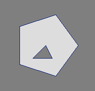
The PolyMesh object may be used to include objects that have been modeled using the polygonal modelling paradigm in Ayam scenes. See the image above for a simple example.
There are just a few special modelling actions for this type of object (see section PolyMesh tools), but its control points can be selected and modified as it can be done with other object types, e.g. curves.
The PolyMesh object is equivalent to the general points polygons primitive of the RenderMan interface. This means, each PolyMesh object may contain multiple general (convex or concave) polygons, which in turn may consist of an outer loop and an arbitrary number of inner loops that describe holes in the polygon (see also the image above, showing a polygonal mesh with one pentagonal face and a triangular hole). The loops use a point indexing scheme to efficiently reuse coordinate values. This general approach requires a so called tesselation to be carried out, in order for the PolyMesh object to be shaded. For the tesselation, Ayam uses routines of the GLU library.
Ayam is able to automatically create face normals for PolyMeshes. They will be calculated while tesselating the PolyMesh and be perpendicular to the plane determined by the first three vertices of the outer loop of a polygon. Furthermore, Ayam supports vertex normals (normals stored for every control point).
Note that storing single triangles in PolyMesh
objects will lead to a real waste of memory. The
merge tool (main menu "Tools/PolyMesh/Merge") can be used
to combine many PolyMesh objects into a single PolyMesh object.
The following table briefly lists some capabilities of the PolyMesh object.
| Type | Parent of | Material | Converts to / Provides | Point Edit |
| PolyMesh | No | Yes | SDMesh | Yes |
The PolyMeshAttr GUI just displays some information about the PolyMesh object:
"NPolys" the number of polygons."NControls" the total number of control points
defined."HasNormals" is 1 if the object uses vertex normals,
else it is 0.PolyMesh objects may be converted to SDMesh
objects using the main menu entry
"Tools/Convert".[∗]
Note that no verification of the usability of the mesh as base mesh for a subdivision surface is carried out. Usually, such meshes have to be manifold and may not contain T-junctions.
PolyMesh objects will be exported as RiPointsGeneralPolygons primitives
(regardless of whether the actual configuration would fit into a simpler
polygonal primitive of the RenderMan interface, e.g. a RiGeneralPolygon).
PV tags are supported.
For scripting interface commands that manipulate PolyMesh objects see section Manipulating PolyMesh Objects.
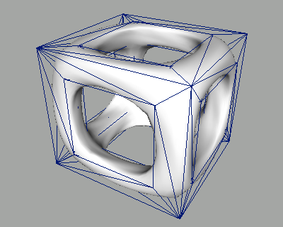
The SDMesh object may be used to include objects that have been modeled using the subdivision modelling paradigm in Ayam scenes (see also the image above).
There are no special modelling actions for this type of object, but its control points can be selected and modified as it can be done with other object types, e.g. curves.
The SDMesh object is equivalent to the Subdivision Mesh primitive of the RenderMan interface. This means, each SDMesh object may contain multiple faces with arbitrary number of vertices that form a polygonal mesh. This polygonal mesh is then successively refined using a subdivision scheme and, depending on the number of refinement (or subdivision) steps, results in a more or less smooth surface. There are several different subdivision schemes, but the scheme currently supported by most RenderMan compliant renderers is named "Catmull-Clark".
Tags may be specified for faces, edges, or vertices to control the subdivision process (e.g. to create sharp corners or edges in the resulting surface). All tags known from the RenderMan interface (hole, crease, corner, and interpolateboundary) are supported by Ayam, but they may currently not be changed by the user.
Unless the "subdiv" plugin (available since Ayam 1.19) is loaded,
Ayam is not able to do the subdivision and show the resulting smooth
surface. All that is shown in wire-frame and shaded views is the original
polygonal mesh.
The following table briefly lists some capabilities of the SDMesh object.
| Type | Parent of | Material | Converts to / Provides | Point Edit |
| SDMesh | No | Yes | PolyMesh | Yes |
The SDMeshAttr GUI just displays some information about the SDMesh object:
"Scheme", is the subdivision scheme, currently available
schemes are Catmull-Clark and Loop.[∗]"Level" is the number of subdivision steps that should
be carried out when subdividing the mesh for preview. This subdivision
needs the "subdiv" plugin."DrawSub" allows to switch between the control polygon
and the subdivided polygon outlines when drawing the mesh."NFaces", the number of faces."NControls", the total number of control points
defined.SDMesh objects may be converted to PolyMesh objects.[∗]
Note however that only the original, unrefined, control
polygon (i.e. the base mesh) will be converted unless the "Level"
attribute is not zero and the "subdiv" plugin is loaded.
SDMesh objects will be exported as subdivision mesh primitives:
RiSubdivisionMesh(...);
These objects create/modify arbitrary other objects from scripts or define entirely new object types via the custom object plugin mechanism.
crtOb NCurve -l 30 -kt 1
sL
for {set i 0} {$i < 30} {incr i} {
    set x [expr $i*cos($i*20.0)/10.0]
    set y [expr $i*sin($i*20.0)/10.0]
    setPnt $i $x $y 0 1
}
|
|

|
Script objects are the most flexible object type of Ayam. They may be used to create new objects, modify existing objects, or realise mechanisms like constraints using small scripts that are embedded in the Script objects themselves.
Those small embedded scripts may employ functionality from Tcl and the Tcl scripting interface of Ayam (see also section Scripting Interface). See also the table above, depicting a simple example script object that creates a NURBS curve and puts the control points of the curve in a spiral in the XY-plane. This example is also distributed with Ayam.
Script objects may also use arbitrary, plugin provided,
scripting languages, like JavaScript, provided by the
"jsinterp" plugin (see also:
JavaScript Scripting Interface).[∗]
The binary and source distributions of Ayam contain several example
scripts for Script objects in the "ayam/bin/scripts" and
"ayam/src/scripts" directories, respectively. In addition,
there are example scene files using Script objects in the
"ayam/scn/scripts" directory, see also
section
Distributed Script Objects.
The following table briefly lists some capabilities of the Script object.
| Type | Parent of | Material | Converts to / Provides | Point Edit |
| Script | Any+ | No | Any+ | No* |
The script of a Script object will be run each time the script is
modified and each time the notification callback of the Script object
is called (e.g. because one of the children of the Script object changed).
As long as the script of a Script object is executed, Ayam will
not process any events except for checking whether the script emergency
hotkey <Ctrl+C>, that may also be used to
escape from infinite loops in the Ayam console, is pressed.
Calling commands and procedures that lead to the processing of
events or that are slow because they manipulate or update the
GUI of Ayam should be avoided. In particular, the following
procedures and commands should not be used: uS, uCR,
uCL, selOb, uP, undo!
As a Script objects script is fired with the notification of said object, and recursive notification is blocked by the Ayam core, the script can not rely on automatic multilevel notification when creating hierarchies of objects, e.g. for tool objects. Instead, the notification of a tool object created by the script has to be triggered manually by the script.
If a script fails, the Script object will be disabled by means
of the "Active" attribute.[∗]
Furthermore, the script line where the error occurred will be
highlighted in the script editor.
Script objects may also create their own property
GUIs for e.g. script parameters.[∗]
This may be accomplished by adding tags of type "NP" with the
name of the new property as value to the Script object (menu entry
"Special/Tags/Add Property").
The script itself is responsible for data
management and property GUI creation (see section
ScriptAttr Property
below).
There is also a tag type to remove properties
("RP").[∗]
Using this tag, the actual script code can be hidden
and thus users are blocked from unintentionally changing it.
Starting with Ayam 1.16, the environment for running Script objects scripts has been refined to allow more complex scripts (that traverse the scene or use the clipboard) to be written. When a script is running,
"CreateAt" and "CreateIn" options are
both disabled (i.e. objects will be created with default transformation
attributes).Script objects will be exported to RIB files as the objects they create/modify.
This section discusses the available Script object types and additional controlling parameters.
"Active" is disabled, the script will not be run.
"Type" is the type of the Script object.
Three types of Script objects are currently available:
"Run", the script will be run and no special action will
take place.
"Create", the script will be run and will create and
parameterise new objects. After running the script, the newly
created object(s) will automatically be moved into the internal data
structure of the Script object. The Script object will look like
and act as an object of the type that the script created.
If the script creates e.g. a NCurve object, the Script object may
be used as parameter object of a tool object that needs a NCurve,
e.g. a Sweep:
+-Sweep
  |-Cross_Section(Script)
  \-Path(NCurve)
"sL" (which performs
a hidden selection in the safe interpreter context).
Consequently, the most simple example script for a Script object
of type "Create" looks like this:
crtOb NCurve
crtOb NCurve
sL
setProperty NCurveAttr(Order) 2
"Modify", if the Script object has child objects,
these child objects will be temporarily moved into the internal data
structure of the Script object. A copy of all child objects will be
created as new children of the Script object. A selection of the
new child objects will be established, then the script will be run.
Usually, the script modifies one of the selected objects (moves control
points, adds tags, or does something similar). Afterwards, the two sets
of objects will be exchanged, the modified objects will be moved to
the internal data structure of the Script object while
the unmodified original child objects will again be child objects of the
Script object. The modified objects will henceforth be provided upstream to
potential parents.
If certain actions in the script shall be restricted to
one of the child objects of the Script object, the
"withOb" command may be used to accomplish this easily.
The Script object will look like and act as an object of the type
of the first child object of the Script object.
If the Script object has e.g. a NCurve object as first child, the
Script object may be used as parameter object of a tool object that
needs a NCurve, e.g. a Sweep:
+-Sweep
  +-Cross_Section(Script)
  | \-NCurve
  \-Path(NCurve)
"Modify" that
needs a single NURBS curve as child object may look like this:
revertC
revertC command directly but provide NURBS curves
(e.g. ExtrNC objects or instances of NURBS curves) the code has to
look like this:
convOb -inplace; revertC
"Script" is the script code.
The corresponding widget is a text widget that allows to directly
edit the code."Paste (Replace)" context menu entry of the text widget.
In contrast to the other property GUI elements, the text widget has
a resize handle in the lower left corner, and a dynamically appearing
scroll bar, see also the image below.
Finally, the font used to display the script may be adjusted using
the corresponding entry from the context menu.
Summary of the context menu entries:
"Clear All" clear the script editor;"Clear Error" clear the error highlight (red background);"Paste (Replace)" replace the entire content of the script
editor with the clipboard content;"Load from file" replace the entire content of the script
editor with a script loaded from a file;"Syntax Highlighting" toggle coloring of script syntax;"Show line numbers" toggle display of line numbers;"Set Font" adjust the font face of the script editor.
If the script has a property GUI it is important to save the property data array between multiple copies of a Script object (to make them truly unique and not operating on the same set of parameters) and to scene files.
This can be accomplished using a comment in the first line of the script. If it looks like this:
# Ayam, save array: <arrayname>
<arrayname> will be saved with
the Script object to Ayam scene files.
The array must contain an entry "SP" that lists all individual
parameters of the Script object. Note that only parameters from this
list will be saved to Ayam scene files.
Note also, that "SP" must never contain "SP". All copies
of a Script object must share the same set of individual vs. shared
parameters. If Script objects need to store differing/individual
amounts of parameter data, lists can be used as individual parameters.
Script objects may also use arbitrary, plugin provided,
scripting languages.[∗]
To switch to a different language, the first line
of the script must be a comment (in the syntax of the other language)
with the keyword "use:" followed by the language name, as
provided by the corresponding plugin, e.g. for JavaScript the first line
should look like this:
/* Ayam, use: JavaScript */
var i, a = 0.5;
for(i = 0; i < 5; i++)
  {
    ...
/* Ayam, use: JavaScript, save array: MyArr */
var MyArr = new Object();
if(!tcleval("info exists MyArr;"))
  {
    MyArr.MyPar = tcleval("set MyArr(MyPar) 0.5;");
    tcleval("set MyArr(SP) {MyPar};");
  }
else
  {
    MyArr.MyPar = tcleval("set MyArr(MyPar);");
  }
  ...
In Ayam versions prior to 1.16 Script object scripts could use any functionality of Tcl, Tk, and the Tcl scripting interface of Ayam which posed a huge security risk. This is no longer the case. Script objects scripts now run in a safe interpreter with reduced instruction set. They can no longer write to the file system, get onto the network, or confuse the application state. Direct access to Tk is also completely blocked, but Script objects still can have their own property GUIs (refer to the examples below).
In particular, the following Tcl commands are not available in the
safe interpreter:
cd, encoding, exec, exit, fconfigure, file,
glob, load, open, pwd, socket,
source, unload; auto_exec_ok, auto_import, auto_load,
auto_load_index, auto_qualify, unknown
(the missing unknown and autoloading facilities
lead to further unavailability of commands normally available via
autoloading, like e.g. parray, history).
The puts command is available in a limited fashion: only access to
the stdout and stderr channels is allowed.
Ayam scripting interface commands that directly manipulate the user
interface are also not available (uS, rV etc.). Please refer to the
documentation of the scripting interface commands about their availability
in the safe interpreter
(see section
Procedures and Commands).
In addition, access to global variables deserving protection like
env, ay, ayprefs is not allowed. In fact, the safe
interpreter has a completely separate set of variables. Transfer of
data between both interpreters must be arranged manually from the
Ayam interpreter (i.e. with scripts that run in the Ayam console).
With the help of scripts, that run in the Ayam interpreter, more commands may be transferred to or made available in the safe interpreter. But this may, of course, open security holes again.
Full access from Script objects to the complete scripting interface
may be re-enabled by recompiling Ayam.
If this is enabled and scene files containing Script
objects are loaded, Ayam will raise a warning dialog, offering to
temporarily disable all Script objects that will be read. The Script
objects will be disabled using their "Active" Script object property
and may be enabled again after careful inspection of the script code
manually or using the main menu entry "Special/Enable Scripts".
Even though, initially, Script objects do not show and use the
Transformations property, they can support transformations under
certain circumstances.
To enable this support, a NP tag with the value "Transformations"
must be added to the Script object (i.e. the Transformations property
must be visible in order to be effective).
Now, the result(s) of the script can, additionally, be manipulated by
the standard interactive modelling actions, like move or scale.
Note, that upon provide or conversion the transformations from the
Script object will be added to the transformations of the objects
created by the script in the same way as by the delegate
transformations tool, which fails for complex setups (e.g. shear
transformations).
However, if the objects created by the script have editable points,
this problem can be avoided by using the "applyTrafo" command
in the script.
Script objects convert to the objects they create/modify
using the main menu entry "Tools/Convert".
When converting in place, some special rules are in effect:
If the script created a master object and instances of this master, normal conversion will not be able to duplicate this relationship (due to the copy semantics of instance objects, see also section Instances and the Object Clipboard). To get around this, just copy the Script object and then use in place conversion on the copy.
Script objects of type "Create" and "Modify" support the standard
caps as lined out in section
Caps Property
and the standard bevels as lined out in section
Bevels Property.[∗]
The boundary names are U0, U1, V0, and V1.
By default, the corresponding properties are not available. To make
them visible, NP tags need to be added to the Script object.
The caps and bevels from the Script object will be added to all created/modified objects that do not possess own caps and bevels already and that support caps and bevels.
This section illustrates the development of a Script object for parametric lines, otherwise unavailable in Ayam.
We start with a simple version that first creates a NURBS curve object with two control points and then places the control points each at +/− half the desired line length on the X-axis.
Just copy the following code to the
Script property of a Script object of type "Create" and activate it.
set length 1
crtOb NCurve -length 2
sL
setPnt 0 [expr {-$length/2.0}] 0.0 0.0 1.0
setPnt 1 [expr {$length/2.0}] 0.0 0.0 1.0

This code works, but if lines of a different length than 1 are needed,
the user must edit the script which is not very convenient and error
prone.
A complete, easy to use, and safe GUI for the length parameter
can be added by changing the script code to:
addScriptProperty LineAttr {{Length 2.0 length}}
crtOb NCurve -length 2
sL
setPnt 0 [expr {-$length/2.0}] 0.0 0.0 1.0
setPnt 1 [expr {$length/2.0}] 0.0 0.0 1.0

The newly inserted call to addScriptProperty does quite a bit
of complicated setup/management code, which is also all too easy
to do wrong, given that there are actually two interpreters involved
and certain things must / must not be done on the first
script run (e.g. after being read from a scene file).
The GUIs created this way are, however, limited to four basic
GUI element types and all members of the respective data arrays
will be saved to scene files.
See also section
addScriptProperty.
The manual but more flexible way of creating/managing a property GUI would look like this:
# Ayam, save array: LineAttrData
if { ![info exists ::LineAttrData] } {
    array set ::LineAttrData {
        Length 1
        SP {Length}
    }
}
if { ![info exists ::LineAttrGUI] } {
    set w [addPropertyGUI LineAttr]
    addParam $w LineAttrData Length
}
set length $::LineAttrData(Length)
crtOb NCurve -length 2
sL
setPnt 0 [expr {-$length/2.0}] 0.0 0.0 1.0
setPnt 1 [expr {$length/2.0}] 0.0 0.0 1.0
To actually see the property GUI, a "NP" (new property) tag
with the value "LineAttr" would also have to be added to the
Script object.
The manual GUI setup code first creates a Tcl array essential to manage the
data of an Ayam object property (LineAttrData). Then, the LineAttr
property GUI is created and a GUI element is added to the GUI using
"addParam".
Note that the "addPropertyGUI" command expects for a property
named "SomePropertyName" a corresponding property data array
named "SomePropertyNameData" to exist.
The GUI setup code should just run once, therefore it checks for the
presence of the variable "LineAttrGUI" (which is created on the first
run of "addPropertyGUI") first.
See also sections
Property GUI Management
and
Global Property Management and Data Arrays
for more information about property GUIs and the Ayam scripting interface.
Finally, to enable saving of the parameter value in the new property
"LineAttr" to scene files, a comment must be prepended to the
script ("Ayam, save array: LineAttrData"), and to enable
multiple and individually parameterised copies of this
Script object, a "SP" entry needs to be added to the
"LineAttrData" array as well.
The complete script is also available as example script file
"scripts/crtlinegui.tcl" in the Ayam distribution.
This example script demonstrates the scene traversal and hierarchy building capabilities available to Script objects since Ayam 1.16.
Create a Script object, and add two children to it, a box and a NURBS curve (order 2, knot type: chordal works best). Then add the following script to the Script object:
# this script needs object type "Modify" and two children:
# a box/sphere and a curve
withOb 1 {estlenNC len}
cutOb
crtOb Clone
goDown -1
pasOb -move
goUp
sL
getProp
set CloneAttrData(NumClones) [expr round($len)]
setProp
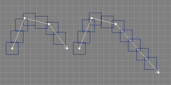
Custom objects are plugins that extend the Ayam capabilities by defining entirely new types of e.g. geometric objects. This may be done easily, because the Ayam core is written in a modelling paradigm independent way.
Custom objects may also define own modelling tools. Those can
usually be found in the "Custom" main menu.
Unlike other modelling helper plugins, custom object plugins
will be loaded automatically with the scene files that contain
such objects. Note, that this only works properly if the preference
option "Main/Plugins" is correctly set.
Several custom object plugins are already distributed with Ayam. Those are documented in the next sections.
The SfCurve object creates a superformula curve from four parameters
named m, n1, n2, and n3 (see also the image below).
The superformula is a generalization of the superellipse; in polar
coordinates it is defined as:
r(t) = (cos((m×t)/4)n2 + sin((m×t)/4)n3)-(1/n1)
where r is the radius and t the angle. The SfCurve object allows
to specify start and end values for t as well as the number of
sample points in between.
The generated NURBS curve is always closed, but the order may be configured
freely.
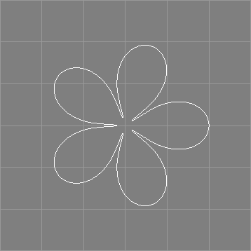
The following table briefly lists some capabilities of the SfCurve object.
| Type | Parent of | Material | Converts to / Provides | Point Edit |
| SfCurve | No | No | NCurve | No* |
The SfCurve object provides the following parameters:
"M", "N1", "N2", and "N3"
control the superformula.
"TMin" is the start angle."TMax" is the end angle.
Note that the angle defined by "TMin" and "TMax" may
actually be larger than 360, as can be seen in the image below:
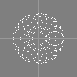
Also note that e.g. setting "TMin" to 1 and "TMax" to 361
may deliver better results than using the default values.
"Sections" is the number of sample points.
Curves with sharp features may need high values of about 100.
"Order" is the desired order of the curve.
"Tolerance" and "DisplayMode".The superformula curve may be converted to an ordinary NURBS curve using the
main menu entry "Tools/Convert".
Furthermore, the superformula curve fully supports the revert, refine, and coarsen operations.[∗]
SfCurve objects never directly appear in RIB output (only indirectly as trim curve).
The BCurve (basis curve) object creates a cubic parametric curve from a number of rational control points and a basis (which is a 4 by 4 matrix).[∗] The basis defines the interpretation of the control points, similar to the bicubic patch mesh primitive of the RenderMan interface, see also section PatchMesh Object. The BCurve therefore represents a range of parametric curves like B-Spline, Bezier, Catmull-Rom, and Hermite splines.
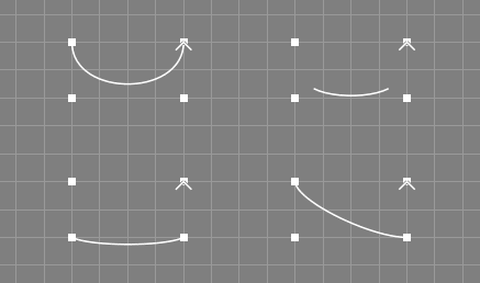
See also the image above depicting simple example curves of some basis types.
The following table briefly lists some capabilities of the BCurve object.
| Type | Parent of | Material | Converts to / Provides | Point Edit |
| BCurve | No | No | NCurve | Yes |
The BCurve object provides the following parameters:
"Closed" determines whether the curve is closed.
"Length" is the number of control points, valid values depend
on the basis type / step below, see also the corresponding
discussion in section
PatchMeshAttr Property.<Control> key is held down.
"BType" is the basis type. The following basis types are available:
"Bezier", "B-Spline", "Catmull-Rom",
"Hermite", "Power", and "Custom".
"Basis" is the basis.
"BStep" is the step size, this value must be 1, 2, 3, or 4.
"Tolerance" and "DisplayMode".The entries "Basis" and "BStep" are only visible, if the
basis type is "Custom".
The basis curve may be converted to an ordinary NURBS curve using the
main menu entry "Tools/Convert".
Furthermore, the basis curve fully supports the revert, open, close, refine, and coarsen operations.[∗]
BCurve objects never directly appear in RIB output (only indirectly as trim curve).
The BCurve object plugin defines a scripting interface command to convert BCurve objects to a different basis, see also section tobasisBC.
The SDCurve (subdivision curve) object creates a curve from a number of non-rational control points.[∗] Subdivision curves are similar to subdivision surfaces, but a polygon is subdivided to a limit curve instead of a polygonal mesh to a limit surface, see also section SDMesh Object.
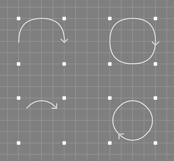
See also the image above depicting four simple example curves.
The following table briefly lists some capabilities of the SDCurve object.
| Type | Parent of | Material | Converts to / Provides | Point Edit |
| SDCurve | No | No | NCurve | Yes |
The SDCurve object provides the following parameters:
"Closed" determines whether the curve is closed.
"Length" is the number of control points.
"Type" is the subdivision method to use, the currently
implemented methods are "Chaikin" and "Cubic"."Chaikin" method inserts two new points
into each section of the original control polygon, all old points are
removed."Cubic" method inserts one new point into each section of the
original control polygon, the original points will not be deleted but
rather moved to the barycenter of the two surrounding new points and
the original point.
"Level" determines the number of iterations of the subdivision
algorithm to carry out.
"SLength" is the number of points generated by the
subdivision algorithm.The subdivision curve may be converted to an ordinary NURBS curve of
order 2 using the main menu entry "Tools/Convert".
Arbitrary curve objects can also be converted to subdivision curves using
the provided conversion tool that is accessible via the main menu entry
"Custom/SDCurve/From Curve". This tool supports NCurve, ICurve,
and ACurve objects directly, all other curve objects need just to provide
their points to be supported.
Furthermore, the subdivision curve fully supports the revert, open, close, refine, and coarsen operations.
SDCurve objects never directly appear in RIB output (only indirectly as trim curve).
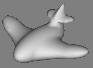
A metaball object is a custom object (see also section Custom Object). It allows you to model with implicit surfaces in realtime.
To start modelling you should first create a "MetaObj" object
using the menu entry
"Create/Custom Object/MetaObj" (if this menu entry is not
available, you have to load the "metaobj" plugin using the menu entry
"File/Load Plugin" first).
"Create/Custom Object/MetaObj" creates a so called meta world with a
single meta component (a sphere) in it. The meta world is represented
by a "MetaObj" object and the component by a "MetaComp"
object which is a child of the "MetaObj" object.
The complete template for the MetaObj object hierarchy, consequently, looks like this:
+-MetaWorld(MetaObj)
  |-C1(MetaComp)
  |-[...
  \-Cn(MetaComp)]
The following table briefly lists some capabilities of the MetaObj and MetaComp objects.
| Type | Parent of | Material | Converts to / Provides | Point Edit |
| MetaObj | MetaComp+ | Yes | PolyMesh | No |
| MetaComp | No | No | N/A | No |
Meta components live only in a meta world, therefore it makes no sense
to create "MetaComp" objects in other places except as a
child of a "MetaObj" object. Type, parameters, and
transformation attributes of the meta components define the function
of an implicit surface. The "MetaObj" object, that represents
the meta world, evaluates this function on a regular three-dimensional
grid and creates a polygonal representation for a specific function
value (the so called threshold value).
The following attributes control the creation of the implicit surface:
"NumSamples" you specify the resolution of the
three-dimensional regular grid, on which the implicit function is
evaluated, in each dimension.
A higher number of samples results in better quality but more polygons
are created and more CPU power and memory are needed. For modelling
you should set this to a lower value of about 40. For final rendering
you may increase this to about 160.
"IsoLevel", defines the threshold value for that a polygonal
representation of the implicit function should be created. Normally, you
should not need to change this value.
"ShowWorld" parameter.New in Ayam 1.5 is an adaptive calculation mode of the implicit
surface. It may be switched on using the new attribute
"Adaptive". In the adaptive calculation mode, Ayam tries
to vary the resolution of the resulting polygonal mesh according to
the features of the implicit surface in order
to capture fine details, even though a coarse grid is used.
This is not done using a successively refined grid but by a
refinement of the triangles created by the original algorithm
(see also XXXX).
You may control the adaptation process using three parameters:
"Flatness", "Epsilon", and "StepSize".
If "Adaptive" is set to "automatic", Ayam will
not use the adaptive calculation while a modelling action is in
progress. This mode has been introduced, because the adaptive mode
may consume a considerable amount of CPU resources.
While modelling with meta balls you may add other "MetaComp" objects
to the "MetaObj" object and parameterise them.
A "MetaComp" object has the following properties.
"Formula" specifies the type of the meta component.
The following types are available: Metaball, Torus, Cube, Heart, and
Custom. The latter gives you the possibility to use your own formulas.
"Negative" you define a component with a
negative effect on the implicit function value.
Negative components are not visible on their own but they are useful
for modelling holes. Just try it.The other parameter are specific to the type of the component:
"Radius" sets the radius of the metaball"EnergyCoeffA", "EnergyCoeffB", and "EnergyCoeffC"
are some parameters for the metaball formula.
Usually you can leave those parameters at their default values.
If you change them, be careful.
"Ri" is the inner radius of the torus,"Ro" is the outer radius of the torus,"Rotate" rotates the torus about 90 degree.
"EdgeX", "EdgeY", and "EdgeZ", let you define the
sharpness of the edges of the cube.
"Expression" is a piece of Tcl script, that represents your
own custom formula for a meta component. The expression may call any
Tcl commands to calculate a field value from the current grid position,
which is given in the global variables "x", "y", and
"z".
The expression simply has to return the calculated field
value.[∗]
Here is an example for a custom expression:
expr {pow($x,4)+pow($y,4)+pow($z,4)}
"f" had to be set to return the field value. This is no longer
the case, but old expression code that ends with
set f [expr ...] is still valid.Metaball objects may be converted to PolyMesh
objects using the main menu entry "Tools/Convert".
Metaball objects will be exported as RiPointsGeneralPolygons primitives (regardless of whether the actual configuration would fit into a simpler polygonal primitive of the RenderMan interface, e.g. a RiGeneralPolygon).
PV tags are currently not supported.
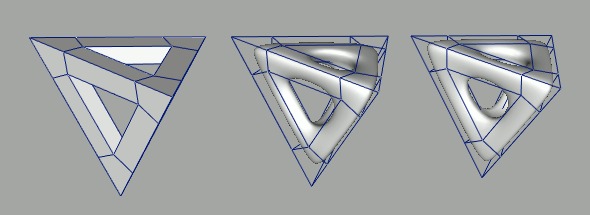
The SDNPatch custom object is available since Ayam 1.16 and allows to model with Subdivision NURBS, which extend the traditional subdivision scheme with knot values and rational coordinates. See also the image above, where in the middle mesh a knot value has been set in the left hand side of the mesh. The SDNPatch plugin is based on libsnurbs by Tom Cashman.
There are some special modelling actions for Subdivision NURBS defined (see below) and there are PLY import/export facilities. Furthermore, there are two conversion operations that convert NURBS patch and PolyMesh objects to SDNPatch objects. Thus, also SDMesh objects may be converted to SDNPatch objects in two steps: first to a PolyMesh then to the SDNPatch.
Please note that the plugin is still in experimental state, there is limited error checking and crashes may occur, if the special modelling actions are used.
The following table briefly lists some capabilities of the SDNPatch object.
| Type | Parent of | Material | Converts to / Provides | Point Edit |
| SDNPatch | No | Yes | PolyMesh | Yes |
The SDNPatchAttr property allows to set the following SDNPatch specific attributes:
"Degree" is the degree of the subdivision NURBS surface,
the only valid values are currently 3, 5, and 7."Level" is the subdivision level, a high level leads to
many polygons and a smooth surface; useful values range from 0 to 5."IsRat" informs, whether the patch
is rational (has any weight values different from
1.0)."NPolys" is the number of polygons generated by the
subdivision algorithm.This section, briefly, explains the special modelling actions defined
for the SDNPatch custom object.
All modelling actions can be started via the "Custom/SDNPatch"
main menu.
Most of these actions require selected faces. To select a face, use the corresponding selection action first, see also section Selecting Faces.
"Face Extrude", new faces are inserted in the mesh at all
edges of the selected faces, the selected faces themselves are displaced
along their respective normals.
This operation has two parameters[∗] that
control the offset of the extrusion operation (parameter "Length")
and a scaling factor applied to the new displaced set of control points
(parameter "Scale"). The length parameter may be negative,
to revert the direction of the extrusion."Face Remove", the selected face and its four neighbors are
removed from the mesh. A new face is created that closes the hole left
by the removed faces. This operation is the inverse of the face extrusion
above."Face Merge", the first two selected faces are removed
from the mesh, the neighboring patches of the second face are connected
to the neighboring faces of the first face.
The decision, which vertices of the faces will actually be connected,
depends on the relative vertex distances: i.e. the faces may need to be
moved near to each other to make clear, how the connection shall be
established."Face Connect", the first two selected faces are removed from
the mesh. The respective holes are then filled by creating a set of new faces,
that connect the respective edges.
The decision, between which vertices of the faces the new faces are built,
depends on the relative vertex distances: i.e. the faces may need to be
moved near to each other to make clear, how the connection shall be
established."Reset All Knots", set all knot values to 1.0 (the default)."Set Knot", set the knot value of the selected edge.
In order to select a edge for
this operation, just select all the control points defining the edge."Revert", reverts all faces."Merge", merges multiple SDNPatch objects into one new."Import PLY", import a PLY file."Export PLY", export the currently selected SDNPatch object
to a PLY file.In addition, there are two conversion operations that convert NURBS patch objects (or NURBS patch providing objects) and PolyMesh objects (or PolyMesh providing objects) to SDNPatch objects.
Note that the PolyMesh to SDNPatch conversion only accepts closed quadrilateral polygon meshes (triangles are omitted) and expects an optimized mesh (i.e. adjacent faces should share the same vertices).
As the standard SDNPatch creation method only creates flat open patches
there is another way to create more complex closed SDNPatch meshes.
The menu entry "Create/Custom/SDNCube" allows to create a SDNPatch
mesh in cube shape with desired number of patches per dimension.
SDNPatch objects may be converted to PolyMesh
objects using the main menu entry "Tools/Convert".
SDNPatch objects will be exported as RiPointsGeneralPolygons primitives
(regardless of whether the actual configuration would fit into a simpler
polygonal primitive of the RenderMan interface, e.g. a RiGeneralPolygon).
PV tags are currently not supported.
Most Ayam objects have standard properties. They are used
to control transformations and common attributes of objects.
The following sections describe the standard properties
"Transformations", "Attributes", "Material", "Shaders",
and "Tags".
Use the "Transformations" property to edit the location, orientation,
and size of an object.
The corresponding property GUI contains the following elements:
"Reset All!" immediately resets all transformation
attributes to the default values.
"Translate_X (_Y, _Z)" is the displacement of the
object from the world origin in X (Y, Z) direction.
"Rotate_X (_Y, _Z)" is the angle (in degrees)
of the rotation of the object around the X (Y, Z) axis.
See below for more information on how to use these
entries."Quaternion" the quaternion that is used to determine
the orientation of the object in space.
"Scale_X (_Y, _Z)" determines a scale factor that will be
applied to the object in the direction of the local X (Y, Z) axis.The transformations are applied to the object in the following order: Scale, Rotation, Translation.
How to use the rotation attributes?
The orientation of an object in space may be expressed using so called Euler angles. This notation (simply three angles determining a rotation about the principal axes of the coordinate system) suffers from a phenomenon called gimbal lock.
To avoid gimbal locks, Ayam internally holds the orientation of an object in a quaternion. This quaternion not only holds information about the angles but also about the order in which partial rotations occurred.
It is important to know, that the values of the angles of the rotation property must not be read in a way that the object will first be rotated around X by x-angle degrees then around Y by y-angle degrees then around Z by z-angle degrees. In fact, no information about the order in which partial rotations occurred may be derived from that three values. This implies, that e.g. the values 0 0 45 may actually denote a different orientation than the very same values 0 0 45.
Rotating an object is easy, simply add the amount about which the object shall be rotated to the value currently displayed in the appropriate entry.
For example, if an object is to be rotated 45 degrees about X and the
x-angle entry displays a 30, enter 75.
Then press the apply button.
If multiple entries are changed the rotations made will be
in the order X (if changed) then Y (if changed) then Z (if changed).
Do not change more than one entry at once unless you exactly
know what you are doing.
Undoing a single rotation works in the same way, just use a subtraction instead of an addition.
Undoing all rotations (resetting the object to its original orientation) is simple too: enter 0 for all three entries at once, then press apply.
To copy just the orientation of an object to other objects
using the property clipboard, all Translate and Scale
property elements should be marked/selected via double clicks,
then "Edit/Copy Property" can be used.
Just marking the Rotate elements and then using
"Edit/Copy Marked Prop"
will not work, because then the quaternion will not be copied
properly.
The "Attributes" property of an object contains currently:
"Objectname", the name of the object. It is also displayed
in the object listbox or tree and may be written to RIB streams.
"Hide", if this attribute is set this object is not drawn.
It may also be excluded from RIB export.
"HideChildren", if this attribute is set, the child objects
of this object are not drawn. This attribute is e.g. used by
"NPatch" objects to prevent the trim curves from being drawn
in normal views.
"RefCount", just displays how many objects point to this
object e.g. through master-instance or object-material relationships.
Objects with a reference count higher than zero may not be deleted.The "Material" property allows you to connect geometric objects
to material objects (see also section
Material Object).
The material property GUI consist of the following elements:
"Clear Material!" immediately clears any connection
of the current object to its material.
"Add/Edit Material!" adds a material to the
current object (if it has none) and immediately selects
the new material object for editing. If the current object
already has a material, this material object is searched for
and selected for editing.
"Materialname" is the name of the material of this object.
If the name is changed, the object will be disconnected from the
old material and connected to the new material.
An easier way to connect geometric objects to material objects is to simply
drop the geometric objects onto the material object using drag and drop
in the tree view.Shader properties are used to attach shaders of a certain type to objects.
The name of the property contains the type of the shader, e.g. light
shaders may be attached using a property named "LightShader" only.
Other types of shaders or shader properties available are: "Surface",
"Displacement", "Interior", "Exterior", "Atmosphere",
and "Imager".
Each shader property GUI, even if no shader is attached to an object,
starts with the "Set new shader."-button. This button allows
to select a new shader of the appropriate type.
If you press the "Set new shader."-button, a dialog with a
list of shaders pops up. If this list is empty, Ayam
is probably not set up properly (or you simply do not have
shaders of the appropriate type). Check the preference setting
"Main/Shaders".
After a new shader has been set, the arguments of the shader will be
parsed and a GUI will be generated to allow the arguments of the shader
to be filled with values.
If the option "KeepParameters" is used, the parameter values of the
previously set shader will be carried over to the new shader, if their
types match.[∗]
The "Delete shader."-button may be used to
delete the current shader from the selected object.
The "Default Values."-button resets all arguments
of the shader to the default values.
See also section
Working with Shaders below.
All other elements of the shader property GUI depend on the currently attached shader, i.e. they represent the arguments of the shader function.
Parsing a shader incorporates detecting the type of the shader and reading the names, types, and default values of all shader arguments.
Shaders will be parsed on the following occasions:
"Scan for Shaders!" button in preferences dialog,"Special/Scan Shaders" menu entry,"ScanShaders" option in "Select Renderer" dialog,"Default Values" button in shader property GUI.Note that currently, Ayam only works properly with shaders that have at most two dots in their file name and that Ayam will simply skip all array arguments (and emit a warning message) while parsing a shader. Those array arguments consequently never appear in the shader property GUIs and RIBs exported by Ayam. Also note that default values for shader arguments of type color will be silently clamped to the range 0-255.
Some shaders use array arguments to define transformation matrices. If this is the case and you have access to the shader source code you may want to modify those shaders to enable working with the transformation matrix carrying shader arguments. To do this, just change all definitions of transformation matrix carrying floating point arrays to real matrices. For instance, if the shader contains a
"float a_matrix_parameter[16]"
change this to
"matrix a_matrix_parameter".
Note that these changes of the shader argument definitions probably also require changes of the shader source code that uses those arguments. Ayam is able to deal with matrices because of their fixed size of 16 float values, and because libslcargs is able to deliver the default values for a matrix (but not for an array!).
If Ayam has been compiled without a shader parsing library
(e.g. without libslcargs), Ayam will parse XML files created
by "sl2xml" from the K-3D project
(see "http://www.k-3d.org/")
instead of compiled shaders.
The "Set new shader."-button will in this case always
open a file requester, allowing you to select a XML file,
that has been created by sl2xml.
Furthermore, the "Default Values."-button will not be available;
you have to use "Set new shader." instead.
From version 1.3 on, Ayam also supports shader parsing plugins to allow parsing of shaders compiled with different shader compilers, see also section Shader Parsing Plugins.
Finally, since version 1.25, there is a script that parses shader source code, see also section Shader Parsing.
The "Default Values."-button resets all arguments of the shader
to the default values.
Additionally, the compiled shader will be parsed again and the property GUI
will be adapted (new shader arguments will appear, removed shader arguments
will disappear).
Therefore, this button is quite handy when dealing with changing
shaders: just edit the shader, recompile it, then back
in Ayam just hit the "Default Values."-button. However, note that
this destroys any possibly carefully adjusted shader argument values.
To keep these old shader argument values select them using double-clicks
on the parameter names in the shader property GUI and then use
e.g. "Edit/Copy Marked Prop"
(see also the description of the property clipboard in section
Properties).
After loading the default values, the saved argument values can
then be re-established using "Edit/Paste Property".
Care should be taken to only copy values with matching types.
Many tool object have a "Caps" property to easily close the
created surface.
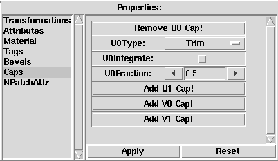
The exact names of the attributes available in this property are
object type specific as each object types boundary names are different:
the boundary names of a Skin object are e.g. "Left", "Right",
"Start", and "End", whereas the boundary names of a NPatch object
are "U0", "U1", "V0", and "V1" (see also the image
above).
When the mouse cursor hovers over any of the Add/Remove buttons, the
corresponding surface boundary is flashing in all views to help decide
where to put the cap.[∗]
To reduce GUI clutter, initially, the Caps property only contains buttons that allow to enable/disable the associated cap and control appearance of further options.
For each enabled cap a menu button will appear that allows to set the corresponding cap type (see section CapAttr Property for more information on the available cap types).
In addition, the Caps property allows to create caps that integrate with
the progenitor surface of the corresponding tool object (after the potential
integration of bevels) via the additional parameter "Integrate".
However, integration is only supported for the cap types
"Simple" and "Simple3D". If integration is enabled and there
is a bevel that is not integrating with the progenitor surface, the
cap will integrate into the bevel instead.
Integration will change the number of provided objects and the parameters
of the progenitor surface.
Similar to Cap objects, MP tags can be set to object to control the middle point in both simple modes (see also section MP (Mean Point) Tag).
Many tool object have a "Bevels" property to easily round the
otherwise sharp borders of the created surface.
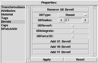
The exact names of the attributes available in this property are
object type specific as each object types boundary names are different:
the boundary names of a Skin object are e.g. "Left", "Right",
"Start", and "End", whereas the boundary names of a NPatch object
are "U0", "U1", "V0", and "V1" (see also the image
above).
When the mouse cursor hovers over any of the Add/Remove buttons, the
corresponding surface boundary is flashing in all views to help decide
where to put the bevel.[∗]
To reduce GUI clutter, initially, the Bevels property only contains buttons that allow to enable/disable the associated bevel and control appearance of further options.
Many attributes of the Bevels property are also available for the
Bevel object (see also
BevelAttr Property).
In addition to those attributes, the Bevels property allows to integrate
the created bevel surface with the progenitor surface of the corresponding
tool object via the additional parameter "Integrate".
Integration will change the number of provided objects and the parameters
of the progenitor surface.
Use the "Tags" property to edit the tags of an object.
See also the image below.
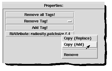
All tag entries have a context menu, where the corresponding tag can be copied/added to the property clipboard.[∗]
Long and multiline tag values will be displayed in abbreviated fashion (with an ellipsis – ...).
The tags property GUI also consists of the following standard elements (see also above image):
"Remove all Tags!" immediately removes all tags
from the object.
"Remove Tag!" is a menu, that allows
to quickly select and remove a single tag from the object.
"Add Tag!" opens a small dialog window, where a new tag type
and value may be entered (see also the image below).
The tag type line has a default value menu, containing the most
important tag types.[∗]"Ok" button, a new entry will be added to the
tags property, displaying the new tag. Just click on the entry to get
back to the dialog, to remove the tag using "Clear" then "Ok",
or to change the type or value of the tag.<Alt-Down> and <Alt-Up>
respectively.
Note that in multiline mode, the <Enter>,
<Return>, and also
<Tab> key will behave differently.

The next sub-sections describe the tag types currently available in Ayam and the plugins distributed with Ayam. Note that foreign extensions and plugins may define their own types.
Tags provide an easy way to attach arbitrary information (e.g. additional RenderMan interface attributes, special attributes for plugins, or even scripts) to objects. A tag consists of two strings, one defining the type and one defining the value of the tag.
Tags may be manipulated via the tags property GUI (see section Tags Property) or the scripting interface (see section Manipulating Tags). In addition, there is a corresponding sub menu in the main menu (see section Tags Menu).
The following two tables contain a compact list of tag names and short explanations for all tag types that are known in Ayam and in all accompanying extensions (plugins); tag types marked with an asterisk (*) are for internal use only.
| Name | Description |
| ANS | After Notify Script |
| AsWire | X3D export control |
| BNS | Before Notify Script |
| BP | Bevel Parameter |
| CP | Cap Parameter |
| CIDR | Importance Driven Rendering |
| CCIDR | Importance Driven Rendering |
| DA * | Script Data Array |
| DANS | Disabled After Notify Script |
| DBNS | Disabled Before Notify Script |
| DC | Depth Complexity |
| HC * | Has Children |
| IDR | Importance Driven Rendering |
| IIDR | Importance Driven Rendering |
| MI * | Material ID |
| MN | Mean Normal |
| mn * | master name |
| MP | Mean Point |
| NM * | Notify Master |
| NO * | Notify Object |
| NoExport | Export Control |
| NP | New Property |
| NT | Normals Tangents |
| Name | Description |
| OI * | Object ID |
| PV | Primitive Variable |
| RiAttribute | RenderMan Export |
| RiDisplay | RenderMan Export |
| R3IDR | Importance Driven Rendering |
| RIDR | Importance Driven Rendering |
| RiHider | RenderMan Export |
| RiOption | RenderMan Export |
| RP | Remove Property |
| SaveMainGeom | Geometry Management |
| SavePaneLayout | Geometry Management |
| SB | Selected Boundary |
| SP | Selected Points |
| TC | Texture Coordinates |
| TI * | Texture ID |
| TM * | Transformation Matrix |
| TP | Tesselation Parameters |
| UMM | U Min Max |
| VMM | V Min Max |
| XML | XML Data |
The tag type "RiAttribute" can be used to attach
arbitrary RenderMan interface attributes to objects.
This is handy if a renderer with lots of RiAttributes
that differ from the standard RiAttributes is in use.
"RiAttribute" tags attached to a geometric object override
"RiAttribute" tags possibly attached to the material object of this
geometric object.
In order to create a tag of type RiAttribute, the type string must be
"RiAttribute". The syntax of the value string is as following:
<attrname>,<paramname>,<paramtype>,<param>
where
<attrname> is the name of the attribute (e.g. "render");
<paramname> is the name of the parameter
(e.g. "displacementbound");
<paramtype> is a single character defining the type of the
parameter (it may be one of
f – float, g – float pair, i – integer,
j – integer pair, s – string, c – color,
p – point); and finally
<param> is the value of the parameter itself (e.g. a
float: "1.2", an integer value: "3", a string: "on", a color: "1,1,1"
or a point: "0.4,0.5,1.0").
Example
Some examples for valid RiAttribute tags:
RiAttribute
render,truedisplacement,i,1

RiAttribute
dice,numprobes,j,3,3

RiAttribute
radiosity,specularcolor,c,0.5,0.5,0.5
Notes
The "RiAttribute" tag handles just a single parameter at once.
Also note that "RiAttribute" tags may be created much more easily
using the menu entry "Special/Tags/Add RiAttribute".
The database of RiAttributes for this GUI may be extended
by editing the ayamrc file, see section
Ayamrc File.
The tag type "RiOption" can be used to attach arbitrary RenderMan
interface options to the scene. This is handy if a renderer with
lots of RiOptions that differ from the standard RiOptions is in use.
However, they will be only used by the RIB exporter if they are attached
to the "Root" object.
The syntax is similar to the "RiAttribute" tag type, see above.
Example
RiOption
radiosity,steps,i,16

RiOption
shadow,bias0,f,0.01
Notes
RiOption tags may be created easily using the menu entry
"Special/Tags/Add RiOption".
Tags created with this GUI will always be added to the "Root" object.
It does not have to be selected when the GUI is used.
Furthermore, the database of RiOptions for this GUI may be extended
by editing the ayamrc file, see section
Ayamrc File.
The tag type "TC" can be used to attach texture coordinates to
objects or materials.
The "TC" tag always contains a list of eight comma separated
float values, that specify a mapping for four 2D points (a quadrilateral)
in texture space from the default values (0,0), (1,0), (0,1), and (1,1)
to the new specified values.
Example
TC
0,0,10,0,0,10,10,10
TC
0,0,0,1,1,0,1,1
TC
0,1,0,0,1,1,1,0
Notes
"TC" tags attached to a geometric object override
"TC" tags possibly attached to the material object of this
geometric object.
The exact behaviour of an object equipped with a "TC" tag
depends heavily on the shader and its use of the texture coordinates.
Note also that using "TC" tags, the texture coordinates
of entire primitives are changed. To change the texture coordinates
of sub-primitives (e.g. of single control points of a NURBS patch)
"PV" (Primitive Variable) tags must be used instead.
To ease setting of "TC" tag values Ayam provides a special graphical
editor as outlined below.
The texture coordinate editor
may be opened using the
main menu entry "Special/Tags/Edit TexCoords" and
lets you edit texture coordinate tags in an intuitive way.
For that, the current texture coordinates are displayed as a black polygon in a canvas with regard to the original (default) values, that are displayed in gray. Small arrows point to positive s and t direction respectively.
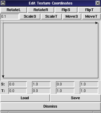
The "RotateR" and "RotateL" buttons shift the coordinate
values between the four points. This results in a 90 degree
rotation of the texture space.
The "FlipS" and "FlipT" buttons flip the texture
coordinate values in s and t direction respectively. This is
useful, if, for example, a texture mapping shall be corrected for
an image that appears upside down.
The next buttons allow to move (using "MoveS" and "MoveT")
and scale (using "ScaleS" and "ScaleT") the texture coordinates
by a specific amount that is given in the first entry field.
The "Load" and "Save" menu buttons allow to:
The texture coordinate dialog is mode-less, it may stay open while modeling.
The tag type "PV" can be used to attach arbitrary data
to geometric primitives and even sub-primitives.
With the help of primitive variables texture coordinates can be attached
to the vertices of a NURBS patch primitive or distinct
colors to the faces or even to single vertices of a polygonal mesh.
In the latter case, the data is properly interpolated by the RenderMan
renderer before it is handed over to the surface shader.
When rendering, all data defined in a "PV" tag is handed over
to the surface shader that is attached to the respective geometric primitive
using additional shader parameters.
For RIB export, proper "RiDeclare" statements will be created
automatically by Ayam.
However, Ayam does not check, whether the shaders actually use the data
from the "PV" tag.
The syntax of the value string of a PV tag is as following:
<name>,<detail>,<type>,<ndata>,<data>
where
<name> is the name of the primitive variable;
<detail> (or storage class) should be one of
"uniform", "varying", "vertex", or "constant";
<type> is a single character describing the type of the
data (one of "c" (color), "f" (float), "g" (float[2]),
"n" (normal), "p" (point), "s" (string), or "v" (vector),
see also the documentation of the "RiAttribute" tag above);
<ndata> is an integer number describing how many data
elements will follow; and
<data> is a comma separated list
consisting of <ndata> elements of type <type>.
Examples
PV
mycolor,constant,c,1,0,1,0
"color mycolor";
PV
mys,varying,f,4,0.1,0.2,0.3,0.4
"varying float mys".
Notes
The following data types are not supported: "i", "j".
Support for the data types "n" (normal), and "v" (vector) was added
in Ayam 1.17.
Not all geometric objects currently honour PV tags on RIB export. The geometric objects currently supporting PV tags are: SDMesh, PolyMesh, PatchMesh, NPatch, and BPatch. Most tool objects that internally create NPatch objects also support PV tags.[∗] Mind that the same set of tags will be used for all surfaces that make up the tool object, e.g. the swept surface, its bevels, and its caps.
Furthermore, the number of data elements, which depends on the detail or storage class, the type of geometric primitive, and the configuration of the geometric primitive is not checked by Ayam. Some RIB writing libraries, however, do verify the numbers and silently omit the primitive variable if there are mismatches. The RIB should be examined for the presence of the primitive variable after export, especially, if PV tags were added or edited manually.
The tag type "RiHider" can be used to choose and parameterise
different algorithms for hidden surface removal when rendering
the exported scene with a RenderMan compliant renderer.
RiHider tags have to be attached to the root object in order to be used.
The syntax of a RiHider tag is quite similar to a RiAttribute tag:
"<type>,<parameterlist>"
where "<type>" is the name of an algorithm and
"<parameterlist>" is a comma separated list
of triplets consisting of name, type, and value of a parameter.
Example
A RiHider tag could look like this:
RiHider
hidden,depthfilter,s,midpoint
Notes
RiHider tags can be overridden when rendering views, see section RIB-Export Preferences.
The tag type "RiDisplay" can be used to add output files of
different type (e.g. containing depth-buffer information)
to the scene or to directly control the output format when rendering
the exported scene with a RenderMan compliant renderer.
RiDisplay tags have to be attached to the Root object in order to be used.
The syntax of a RiDisplay tag is as follows:
"<name>,<type>,<mode>,<parameterlist>",
where
"<name>" is a file or device name,
"<type>" specifies the destination of the image data
(e.g. screen or file),
"<mode>" specifies which information should be stored or displayed
(e.g. color values: rgb, or depth values: z), and
"<parameterlist>" is a optionally present comma separated list
of triplets consisting of name, type, and value of a parameter.
Example
A RiDisplay tag to add output of the depth-buffer information to the
file "imagez.tif" could look like this:
RiDisplay
imagez.tif,file,z
Notes
The name will be automatically changed to "+name" on RIB export
if it does not already start with a plus (except for the very first
RiDisplay statement issued).
The tag type "AsWire" switches export of certain objects
from surface to wire-frame mode.
The value string of this tag is ignored. All
that counts is the presence of the tag.
Note that only X3D export honours this tag.
The tag type "NoExport" can be used to exclude certain objects
from exported RIBs. The value string of this tag is ignored. All
that counts is the presence of the tag. Child objects of objects
with the "NoExport" tag will also be excluded from the RIB.
Since Ayam 1.6, light objects also honour the "NoExport" tag.
Note that regardless of potentially present "NoExport" tags,
RIB archives will be created for all referenced objects all the
time (even if "NoExport" tags are added to all instances).
The tag type "SaveMainGeom" can be used to save the geometry
of the main window and the toolbox window (if open) to a scene
file. For that the scene saving code checks for the presence of
a "SaveMainGeom" tag for the Root object and fills it with
the current geometry information. The scene reading code checks
for the presence of a "SaveMainGeom" tag for the Root object
after replacing a scene and re-establishes the geometries of
main and toolbox window.
This tag is only filled with meaningful data and the geometry is only restored if Ayam is in multi window GUI mode.
The tag type "SavePaneLayout" can be used to save the relative
sizes of the internal windows of the main window when Ayam runs in
the single window GUI mode to a scene file.
For that the scene saving code checks for the presence of
a "SavePaneLayout" tag for the Root object and fills it with
the current geometry information. The scene reading code checks
for the presence of a "SavePaneLayout" tag for the Root object
after replacing a scene and re-establishes the geometries of the
internal windows.
This tag is only filled with meaningful data and the pane layout is only restored if Ayam is in single window GUI mode.
The tag type "TP" can be used to save tesselation parameters
to objects of type "NPatch" (and objects that may be converted
to "NPatch" objects). Those tesselation parameters
will be used when the NPatch object is tesselated for e.g. a
conversion to a PolyMesh object. The syntax of the TP tag is:
"<smethod>,<sparamu>,<sparamv>[,<refinetrims>]"
where
<smethod> is an integer value between 1 and 6,
describing which sampling method to use (1 – ParametricError,
2 – PathLength,
3 – DomainDistance,
4 – NormalizedDomainDistance,
5 – AdaptiveDomainDistance, and
6 – AdaptiveKnotDistance)
and
<sparamu> and <sparamv> are float values
describing the respective parameter value for the chosen sampling
method. The second parameter value is ignored for the sampling methods
1 and 2.
The last value, "refinetrims", is an integer between 0 and 5
controlling how many times the trim curves are to be refined before
tesselation for improved tesselation fidelity along trim edges.
The "refinetrims" value may be omitted and defaults to 0.
Note that the syntax of the "TP" tag changed in Ayam 1.9,
the old syntax only allowed one parameter.
TP tags may be easily created using the tesselation GUI, that can
be started with the main menu entry "Tools/Surface/Tesselate"
(see also section
Tesselation Tool).
Example
A TP tag could look like this:
TP
1,0.5,0.6
The tag type "DC" is only used by the AyCSG CSG preview plugin
to store the depth complexity of CSG primitives.
The syntax of the DC tag is:
"<dcval>"
where "<dcval>" is a positive integer value describing the
depth complexity of the CSG primitive. See also section
CSG preview using the AyCSG plugin
for more information regarding the depth complexity value.
Example
A DC tag (valid for e.g. a torus) could look like this:
DC
2
The tag type "NP" (new property) may be used to add new property
GUIs to single objects. The value of the tag is the name of a new
property. The necessary code to manage the property data and the
windows that make up the property GUI itself have to be present in
the Tcl context of Ayam before the user clicks on the new property in the
property list box.
Example
NP
Transformations
Any script controlled property GUI of a Script object must also be enabled using a NP tag like this:
NP
MyProperty
Notes
NP tags can be managed more easily using a specialized dialog that
is available in the main menu "Special/Tags/Add Property".
The tag type "RP" (remove property) may be used to remove GUI access
to a property from single objects. The value of the tag is the name of the
property to be removed. The GUI access will be blocked by simply omitting
the property from the property listbox.
Note well: the property is still present and active in the objects themselves
and values may still be set using the scripting interface.
Example
RP
Script
"NP" tag, to allow
direct control of script parameters. This way, the user does not
see the script (code), just a clean parameter GUI.
Here is another example: the tag
RP
Transformations
Notes
RP tags can be managed more easily using a specialized dialog that
is available in the main menu "Special/Tags/Remove Property".
The tag type "BNS" (before notify script) may be used to add scripts
to an object, that will be run before the notification of
that object starts.
A notification, in turn, will be executed because e.g. one of the children
of the object changed (see also section
The Modelling Concept Tool-Objects).
When the script runs, the respective object with the BNS tag will already
be selected. Current level and selection will be restored when the
script finishes, i.e. neither needs to be done by the script.
Example
A simple BNS tag could look like this:
BNS
puts "notify callback about to fire"
A more useful example (that is also available as example scene
"ayam/scn/scripts/bnstag.ay"):
BNS
getProp;
set ::RevolveAttrData(Sections) [expr int($::RevolveAttrData(ThetaMax)/10)];
setProp
int() is needed because the C code for the
setProp command of the RevolveAttr property only looks for integer
data in the variable Sections and without int() the variable
would contain incompatible floating point data.
A second similar example would be:
BNS
getProp;
set ::ACurveAttrData(ALength) [expr int($::ACurveAttrData(Length)/2)];
setProp
ALength parameter
of a ACurve object from the number of data points to approximate. When this
tag is added to a ACurve object, the interactive insert/delete point actions
can be used more freely.
Here is another shorter example; the BNS tag
BNS
applyTrafo -all
Notes
In Ayam versions prior to 1.16 BNS tag scripts could use any functionality of Tcl, Tk, and the Tcl scripting interface of Ayam which posed a huge security risk. This is no longer the case. BNS tag scripts now run in a safe interpreter with reduced instruction set. They can no longer write to the file system, get onto the network, or confuse the application state, see also section Safe Interpreter. Consequently, the warning dialog that appeared when files with BNS tags were loaded is also gone.
The original functionality can still be re-enabled by recompiling Ayam.
If this is enabled and scene files containing BNS
tags are loaded, Ayam will again raise a warning dialog, offering to
temporarily disable all such tags that will be read for obvious security
reasons.
To disable a BNS tag, Ayam simply changes its type from "BNS"
to "DBNS" (disabled before notify script).
It will not be executed then.
Disabled notify script tags may be enabled after careful inspection
by simply changing their type back to "BNS"
or by using the main menu entry "Special/Enable Scripts".
If the script of a BNS tag fails, the tag will be disabled by changing the type to DBNS.[∗]
Also note that BNS tag scripts must not change the scene hierarchy, i.e. they must not create or delete objects or use the object clipboard.
The tag type "ANS" (after notify script) may be used to add scripts
to an object, that will be run after the notification of
that object completed.
The notification, in turn, will be executed because e.g. one of the children
of the object changed (see also section
The Modelling Concept Tool-Objects).
When the script runs, the respective object with the ANS tag will already
be selected. Current level and selection will be restored when the
script finishes, i.e. neither needs to be done by the script.
Example
A simple ANS tag could look like this:
ANS
puts "notify callback completed"
Notes
In Ayam versions prior to 1.16 ANS tag scripts could use any functionality of Tcl, Tk, and the Tcl scripting interface of Ayam which posed a huge security risk. This is no longer the case. ANS tag scripts now run in a safe interpreter with reduced instruction set. They can no longer write to the file system, get onto the network, or confuse the application state, see also section Safe Interpreter. Consequently, the warning dialog that appeared when files with ANS tags were loaded is also gone.
The original functionality can still be re-enabled by recompiling Ayam.
If this is enabled and scene files containing ANS
tags are loaded, Ayam will again raise a warning dialog, offering to
temporarily disable all such tags that will be read for obvious security
reasons.
To disable a ANS tag, Ayam simply changes its type from "ANS"
to "DANS" (disabled before notify script).
It will not be executed then.
Disabled notify script tags may be enabled after careful inspection
by simply changing their type back to "ANS"
or by using the main menu entry "Special/Enable Scripts".
If the script of a ANS tag fails, the tag will be disabled by changing the type to DANS.[∗]
Also note that ANS tag scripts must not change the scene hierarchy, i.e. they must not create or delete objects or use the object clipboard.
The tag types "UMM" (u min max) and "VMM" (v min max) may
be used to store additional parametric domain trimming values to
NURBS curve and NURBS patch objects. Note that the GLU NURBS display
modes do not honor those tags, but some export plugins do (RIB,
Wavefront OBJ, 3DM (Rhino)).
Those tags will also be created by RIB import or Wavefront OBJ import.
Example
An UMM tag could look like this:
UMM
0.4,0.6
The tag type "BP" (bevel parameters) is used by all bevel
supporting tool objects to store their bevel parameter information.
See also sections
Bevels property and
BevelAttr Property.
The syntax of the BP tag is:
"<side>,<type>,<radius>,<revert>"
<side> is an integer value from 0 - 3
defining the side of the surface, to add the bevel to,<type> is an integer value defining
the type of the bevel,<radius> is a floating point
value defining the radius of the bevel, and<revert>
is either 0 or 1 and may be used to revert the bevel.
Example
A BP tag could look like this:
BP
0,0,0.1,0
The tag type "CP" (cap parameters) is used by all cap
supporting tool objects to store their cap parameter information.
See also sections
Caps property and
CapAttr Property.
The syntax of the CP tag is:
"<side>,<type>,<integrate>,<fraction>"
<side> is an integer value from 0 - 3
defining the side of the surface, to add the cap to,<type> is an integer value from 0 - 3 defining
the type of the cap,<integrate> determines whether to integrate the cap into the
progenitor surface (0 or 1)<fraction> a floating point parameter value for the Simple3D cap
type.
Example
A CP tag could look like this:
CP
0,0,0,0.5
The tag type "MN" (mean normal) can be added to the Bevel object
to control the mean/target normal of the "RoundToNormal"
bevel mode.
The tag value is a list of three comma separated floating point numbers,
a 3D vector. The vector does not have to be normalized.
Example
A MN tag could look like this:
MN
0.0,1.0,0.1
The tag type "MP" (mean point) can be added to the Cap object
or objects with caps to control the middle point of the "Simple"
and "Simple3D" caps. This is useful if e.g. the automatically
calculated mean point of the parameter curve is off.
The tag value is a list of three comma separated floating point numbers,
a 3D vector, followed by an integer value between 0 and 3 designating
the cap. On Cap objects, the cap number may be omitted.
Example
A MP tag could look like this:
MP
0.5,0.25,0.1,0
The tag type "SB" (selected boundary) is used by the
select boundary action(s) to store their results, but it can
also be created manually or by other means.
The tag supports two notations, a simple one, consisting of an
integer value and a complex one, where an object index and a
boundary index are provided. The latter needs to specified for
tool objects that provide multiple NPatch objects.
The integer values will be interpreted in the following way: 0 – u0, 1 – u1, 2 – v0, 3 – v1, 4 – complete boundary (always untrimmed!), 5 – first trim curve, etc.
Examples
A SB tag in simple notation could look like this:
SB
1
SB
o:2b:4
Tags of type "PP" carry projection parameters. They can be
used to guide the 3D projection used by e.g. Trim objects in
3D scaling mode.
The tag value is a comma separated list of numeric values,
the first six are integer values and the last one is a floating
point value, the corresponding parameter names are:
direction, trim, poly, qfu, qfv, qfc, threshold
see section
Project Curve To Surface Tool
for an explanation. The value list may contain empty slots and can also
be truncated, leading to the use of default or previously set values,
if available.
The default values are:
0, 0, 0, 100, 100, 100, 0.0.
These tags can be added to Trim or individual curve objects, but
when added to curve objects, the qfu/qfv parameters will
currently not be used.
Examples
A PP tag could look like this:
PP
,,1
PP
,,1,,,10E-8
The tag type "XML" can be used to enrich XML based export
formats with arbitrary user defined data (attributes and
nodes).[∗]
It can currently only be added to Material and NURBS surface objects
for X3D export
(see also section
X3D (Web3D) Export).
The value string of this tag must be a valid XML node hierarchy
where the outer node specifies the target node of the XML data.
Attributes of the outer node will be added to the target XML node
for export, already existing attributes will be overwritten
(i.e. the XML data tag will be processed after the XML export
converted the corresponding Ayam object to a XML node hierarchy).
Likewise, all child nodes of the outer node will be added to the
matching target XML node. CDATA sections are also supported
properly (this is important for GLSL shader source code).
Examples
XML tags could look like this:
XML
<Material shininess='0.7'/>
to add the shininess attribute to a Material.
XML
<Appearance>
<ComposedShader language='GLSL'>
...
</ComposedShader>
</Appearance>
to add a GLSL shader to a Material.
The following tags are used by Ayam internally only; they will not appear in the tags property GUI and they can not be deleted or changed using the scripting interface.
This tag is used by the RIB exporter and the scene storage facility to establish links between instance objects and the master objects they are pointing to.
This tag is used by the RIB exporter and the scene storage facility to establish links between material objects and the objects they are assigned to.
This tag is used by the scene storage facility.
Internal binary tag to store transformation matrices, used by the AyCSG plugin.
Internal tag used by the X3D import/export plugin. Renamed from mn since Ayam 1.26.
Internal tag used by the notification mechanism.
These tags are internal binary tags that transport the notification across the scene.
This tag is an internal binary tag that carries normals and tangents for curves extracted from surfaces.