DRAFT
This section describes the user interface of Ayam.
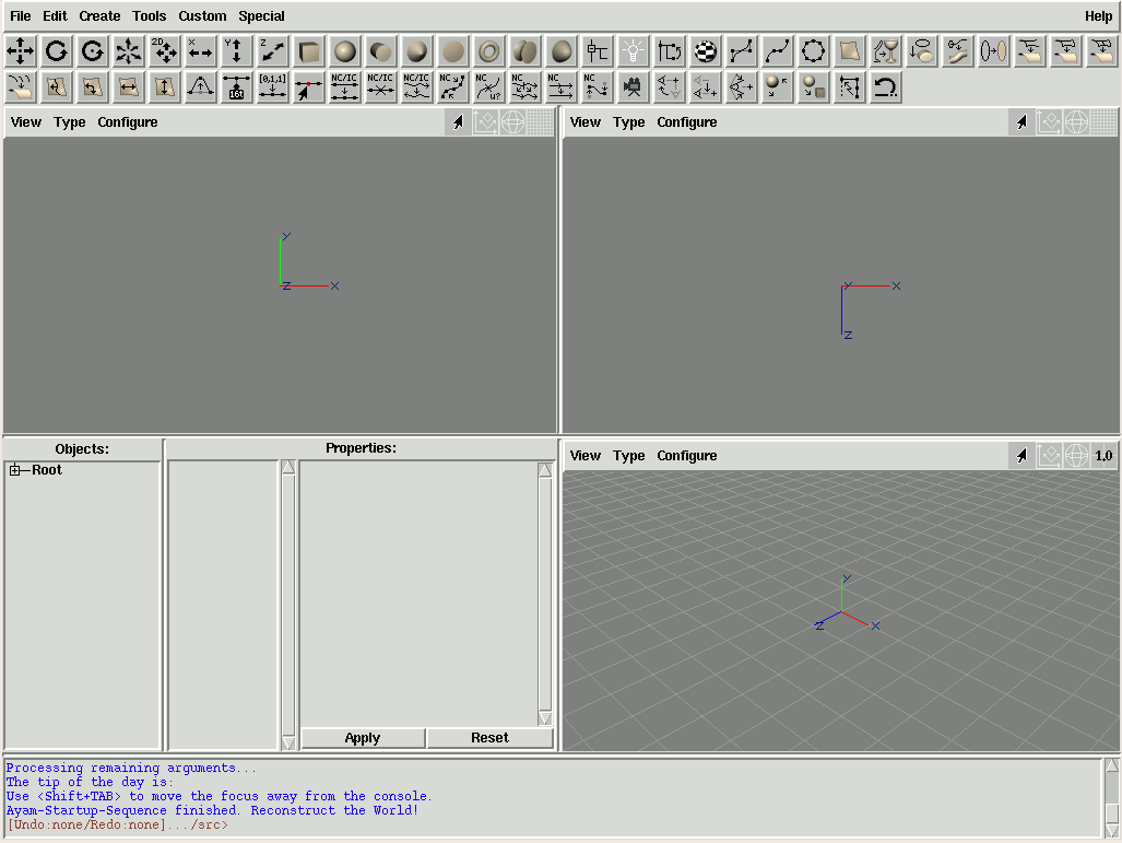
Until Ayam 1.14 all windows were always separate top level windows – a so called floating windows GUI mode. Since version 1.14, a new GUI mode is available where the main window, three view windows and the toolbox are integrated in one top level window. This mode is called single window GUI mode, see also the image above. The new single window GUI mode is enabled by default. All sub windows are in panes, the space occupied by a sub window may be adjusted by dragging the mouse at the borderlines of the panes. The number of views is not limited to three, albeit all extra views will become extra top level windows.

The user interface of Ayam is split into three types of windows: a main window, a toolbox and an arbitrary number of view windows. The main window displays the object hierarchy and allows to edit object properties. The toolbox window is for easy creation of objects and starting of modelling actions and tools. The modelling actions are then carried out in view windows, where also the scene is displayed.
The next sections document the three types of windows (main, toolbox, and views) in detail.
The main window is split into three major areas:
"Objects:""Properties:"
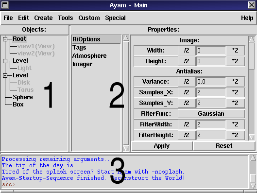
The relative sizes of the three areas are managed by a so called paned geometry management. To change the relative size of the console, move the mouse pointer to the upper border of the console until the pointer changes and then drag the border. The same goes for the right border of the objects section.
The default representation of the object hierarchy is a tree view.
The second available representation is a simple listbox (as known from
"The Mops").
The label "Objects" may be used to switch between the two
representations of the object hierarchy quickly (using a double click).
It is also possible to switch between both representations
using the context menu.
The two representations have very different properties regarding speed, use of resources, and versatility. The tree is, due to the drag and drop operations, much more versatile but also slower.
Both representations manage a so called "current level".
This level is the scene level that is displayed in the object listbox.
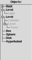
In the tree view the current level is drawn in black while all
other levels are grayed out. Selection of objects
may take place in the current level only!
After the start-up of Ayam you will notice, that there is a first
object called "Root" in the top level of the scene, even though the
scene seems to be empty.
See section
Root Object for more
information regarding this special object, and what it is good for.
Note, that this object can not be deleted or copied.
The object tree view is quite complex and may be slow on slow machines (of the Pentium 90 class), especially when dealing with scenes that contain many objects. This should not be a problem nowadays. Nevertheless, Ayam tries to keep tree update delays as low as possible, but this works only if the scene uses the hierarchy and changes happen in sub levels (not the root level). Further speedups may be achieved with the help of the DTree script (see section Dynamic Tree).[*]
In the tree view, objects may be selected using the left mouse button.
Multiple selection of objects is possible by holding down the
<Shift> or <Ctrl> key while clicking on objects.
Double clicking on objects with child objects toggles display of the child level. The same may be accomplished using single clicks on the well known plus/minus symbols in front of the name of those objects.
Drag and drop operation is also possible to move objects in the hierarchy and to initiate special actions like connecting materials to objects. However, this last feature is documented in section Objects, Properties, and Tags as it is object type specific.
The rightmost mouse button opens a context menu with basic tree and clipboard operations:
"Tree/Rebuild" completely removes the tree nodes, rebuilds
the hierarchy, makes the top level current, and clears the object selection,
"Tree/Expand All" opens all nodes with child nodes,
"Tree/Collapse All" closes all nodes with child nodes,
"Tree/Toggle Selected" toggles display of all sub-levels
of the selected objects,
"Switch to Listbox" removes the tree view and replaces it
with the object listbox (see below).
"Deselect Object" deselects the currently selected
object(s).
"Copy Object", "Cut Object", "Paste Object", "Delete Object"
are standard clipboard operations as documented in
section
Main Menu.
"Help on Object" displays the help of the selected
object.The scene may also be navigated and objects may be selected using the keyboard: [*]
<Up> and <Down> move the selection to the previous
or next object in the current level.
<Shift-Up> and <Shift-Down> will not move the
selection, but rather extend it in the respective
direction.[*]
<Home> and <End> select the first
or last object in the current level,
<Shift+Home> and <Shift+End>
extend the selection to the first or last object in the current
level respectively.[*]
The Root object, however, will always be omitted.
<Right> enters the (first) selected object,
<Left> enters the parent level,
<Ctrl+a> and <Ctrl+n> select or de-select
all objects in the current level. If the current level is the root level,
the Root object will not be selected by <Ctrl+a>.
<Space> toggles display of the child objects of the
selected object(s).
<Shift+Space> toggles display of all sub-levels of the
selected object(s).[*]
<+> opens all sub-levels of the
selected object(s).[*]
<-> closes all sub-levels of the
selected object(s).[*]
<Alt+Up> and <Alt+Down> shuffle the
selected objects in the current level in the respective direction,
unless the root object is selected and unless the first object is
selected for up-movement or the last object for
down-movement.[*]
<^> moves the focus to the first view
(in single window GUI mode).[*]
If those shortcuts do not work you may need to move the keyboard
input focus away from (internal) view windows, the property GUI,
or the console using <Tab> or <Shift+Tab>
first.
Another way of moving the focus (and cleaning up the application state)
is by using the <Esc> key:
In property GUIs and the console, pressing <Esc> moves the focus
away to the main window or object selection window.
Pressing <Esc> twice in a view window
will also reset the focus to the main window / object selection
window.[*]
Pressing <Esc> twice in the object selection
window will additionally clear the selection (this implies
removal of the currently displayed property GUI) and change the
current level to the root level.
Thus, if you feel lost anywhere in Ayam, just press <Esc>
twice or thrice.
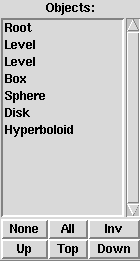
The object listbox displays the object hierarchy of the current scene. Using this listbox you may browse through the hierarchy of the scene with your mouse and you may select one or more objects.
Browsing and selecting should be very intuitive:
Use a double click to enter a level (or an object with child objects),
use a single click to select objects, multiple objects may be selected using
click and drag, or holding down the <Shift> or <Ctrl>
key while clicking.
Keyboard operation is also possible if the listbox has the
input focus.
A ".." is displayed as the first element of the current level
if you are "inside" a level or another object.
A double click on the ".." takes you to the parent level.
The buttons below the listbox may be used to change the selection or
to quickly jump through the hierarchy. They should be self explanatory.
The rightmost mouse button opens a small context menu:
"Switch to Tree" removes the listbox and replaces it
with the tree view (see above).
"Copy Object", "Cut Object", "Paste Object", "Delete Object"
are standard clipboard operations as documented in
section
Main Menu.
"Help on Object" displays the help of the selected
object.The scene may also be navigated and objects may be selected using the keyboard: [*]
<Up> and <Down> move the selection to the previous
or next object in the current level.
<Shift-Up> and <Shift-Down> will not move the
selection, but rather extend it in the respective
direction.[*]
<Home> and <End> select the first
or last object in the current level,
<Shift+Home> and <Shift+End> extend the selection
to the first or last object in the current level
respectively.[*]
The Root object, however, will always be omitted.
<Right> enters the (first) selected object,
<Left> enters the parent level,
<Ctrl+a> and <Ctrl+n> select or de-select
all objects in the current level. If the current level is the root level,
the Root object will not be selected by <Ctrl+a>.
<Alt+Up> and <Alt+Down> move the
selected objects in the current level in the respective direction,
unless the root object is selected and unless the first object is
selected for up-movement or the last object for
down-movement.[*]
<^> moves the focus to the first view
(in single window GUI mode).[*]
If those shortcuts do not work you may need to move the keyboard
input focus away from (internal) view windows, the property GUI,
or the console using <Tab> or <Shift+Tab>
first.
Another way of moving the focus (and cleaning up the application state)
is by using the <Esc> key:
In property GUIs and the console, pressing <Esc> moves the focus
away to the main window or object selection window.
Pressing <Esc> twice in a view window
will also reset the focus to the main window / object selection
window.[*]
Pressing <Esc> twice in the object selection
window will additionally clear the selection (this implies
removal of the currently displayed property GUI) and change the
current level to the root level.
Thus, if you feel lost anywhere in Ayam, just press <Esc>
twice or thrice.
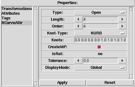
The listbox right next to the object hierarchy displays the properties of the currently selected object.
If there are multiple selected objects, the properties listbox will display no properties at all.
Unlike the object tree/listbox, where multiple entries can be selected, only one property may be selected. If a property is selected, the associated GUI will be shown in the appropriate area (on the right hand side).
Also the keyboard may be used to select properties:
just press one of the <0>-<9> keys (most comfortably
using the numeric keypad). <0> always selects the last and
often the only object type specific property, whereas <1>
selects the first property, which often contains the standard
transformations.[*]
The properties listbox also has a context menu. The entries in this menu allow to:
All property GUIs use more or less standardized GUI elements that are organized in list form, see also the image above. The lists may be scrolled if they get too long to fit into the window.
What properties exactly will be shown, and how the GUIs look alike depends on the selected object and the selected property. This is documented comprehensively in section Objects, Properties, and Tags.
If Ayam is in floating windows GUI mode and the elements of the current
property GUI do not fit horizontally into the screen space that is
defined by the main window size, Ayam can automatically resize the
main window. This behaviour may be controlled using the preference setting
"AutoResize" (see section
Preferences).
If an object and a property are selected and a different object is selected,
the property GUI that has the same index as the previously selected
property in the properties listbox will be selected and shown. This is
not necessarily a property of the same type.
To avoid that or to clear the property GUI for fast browsing through the
scene you may either double click on the "Properties" label, hit the
<Esc> key three times, or use the context menu of the properties
listbox to de-select the current property.
The various things that may be changed using a property GUI
will normally not be applied to the selected object until the
"Apply"-button is pressed.
However, holding down the "Shift" button while
interacting with the property GUI or pressing the "Return" key
when entry widgets have the keyboard input focus will lead
to an instant application of all changed
values.[*]
Note that property GUIs of custom objects may offer interactive
elements that also do an instant "Apply" operation. But most property GUI
elements of the core objects of Ayam do not change anything until
the "Apply"-button is used.
All changes to the arguments of a property that have been made since
either opening the property or the last "Apply" operation (whatever
was last) can be reverted with the "Reset"-button.
Mind that this does not use the undo mechanism of Ayam but rather copies
Tcl data, just like the property clipboard.
If a property GUI element has the keyboard input focus (it is then usually
displayed with a black rim around it), all the keyboard shortcuts for
the main menu and scene navigation will have no effect until the
keyboard input focus is moved away from the property GUI. This may be
accomplished easily using the <Esc> key.
A property may be copied and pasted to another object, see the
"Edit" menu. You can also paste property values to different types
of properties (e.g. pasting parameters from a surface shader to the
displacement shader, or pasting a radius value from a sphere to a disk)
using "Paste to selected" in the
"Special/Clipboard" sub-menu.
Pasting a property to multiple selected objects does work too. This is a great way to apply e.g. a parameterised surface shader to a bigger number of material objects, without going the long way of setting a new shader and entering parameters for it for every material object.
Since you may not want to copy and paste whole properties all the time, you may even mark single parameters with a double click on the labels of the parameters. The selected parameters will then be preceded by an exclamation mark (!) in the property GUI.
If this property is then copied, all marked parameters will be omitted.
It is also possible to copy just the selected parameters using
"Copy Marked Prop".
A simple example for such advanced use of the property clipboard:
Our task is to give a big number of material objects the same color, but they already have different opacity settings. Copying the complete attribute property would destroy the individually adjusted opacity values. We can solve this by copying just the color attribute, but leave all other attributes as they are:
"Attributes" property GUI. (Do not forget the "Apply" button!)
"Color"; it should read "!Color" now.
"Copy Marked Prop" in the "Edit" menu or the
hot key <Ctrl+I>.
"Paste Property" or <Ctrl+V>.
Special care must be taken when pasting incomplete properties to objects which do not have complete properties already. Do not paste an incomplete shader property to an object which does not already have the same shader.

The third part of the main window is the console. The console is mainly for unobtrusive text output (informative, warning, and error messages). If something does not work as advertised, the console may be worth a look.
The console captures the stderr and stdout channels of the
Tcl-interpreter Ayam is running in. It is also possible to
redirect all internal Tcl error messages, that would normally
cause a Tcl error dialog window to appear, to the console using
the preference setting "Misc/RedirectTcl"
(see section
Miscellaneous Preferences).
Furthermore, commands or even complete new Tcl procedures can be directly entered into the console. However, this is a feature for an advanced user that studied section Scripting Interface. You need to explicitly click into the console to give it the input focus and thus enable input.
An important thing to know is that the keyboard shortcuts for the
various main menu entries do not work if the console has the input
focus. Instead, other keyboard shortcuts (related to the console)
are in effect.
How do you get out of this? Simply press <Shift+Tab> or
<Esc> to move the focus away from the console and enable
the main menu shortcuts again.
Note that the <Tab> key alone does not move the focus away
from the console.
<Tab> instead completes names of files, commands (procedures),
variables, and widgets.
You may try this out by typing tip in the console,
then press <Tab>.
The console automagically completes tip to tipoftheDay
(the procedure that prints out the tip of the day, just try it).
Remember that many commands of the Ayam scripting interface work
in background: without update of object selection widget, property GUI or
redrawing of view windows. But it is possible to enforce an immediate update
of the GUI and redrawing of all views by using <Shift-Enter>
instead of <Enter> when entering commands.
Another simple demonstration of the consoles capabilities:
forAll {movOb $i 0 0; rotOb [expr $i*10] 0 0}This example uses three procedures:
forAll: allows to execute
a command for each of the selected objects, or for each object in the
current level if no objects are selected.movOb: moves the selected object(s).rotOb: rotates the selected object(s).See section Scripting Interface for a listing of all the available commands.
Note that the example uses a side effect (the variable "i" that
holds the index of the currently processed object) to calculate
the amount of the movement and rotation.
For more information regarding the console, please refer to the appropriate documentation by the original author Jeffrey Hobbs (see the console context menu, that can be opened with the right mouse button).
This section discusses the main menu bar.
Note that many menu entries have keyboard shortcuts that are displayed
in each entry. But those shortcuts only work if the main window
has the keyboard input focus and the input focus is not in the
console or in a property GUI element (i.e. a data entry field).
Hit <Esc> to set the focus to the object selection
widget and thus enable the main menu keyboard shortcuts.
These keyboard shortcuts may be adapted using the "ayamrc" file
(see section
Ayamrc File).
Another way of navigating the menu is via the <Alt> or
<Menu> key, pressed together with the various underlined
characters in the menu entries. Once a menu is open, it may also be
navigated with the cursor keys. The <Return> key invokes
the currently selected menu entry and the <Esc> key closes
the menu.
The "File" menu deals with standard file operations:
"New", clears the current scene (deletes all objects) and reloads
the working environment."Open", clears the current scene and closes all views,
then loads a new scene from disk.
All objects from the file
will be read. A backup copy of the file will be made before loading
(depending on the preference setting "Main/BakOnReplace").
See section
Opening Scene Files
for a more detailed discussion.
This operation cannot be undone!
Also files supported by any of the import plugins
may be imported using this route.[*]
Note that this only works if the selected file has a file name extension.
The appropriate plugin will
be loaded automatically (from the list of plugin directories in the
preferences) if needed and the import options dialog of the plugin
will be opened, with the "FileName" option already set.
Mind that in this case, no backup copy of the file will be made.
See also section
Import and Export.
"Insert", inserts the objects and views of an Ayam scene file
into the current scene.
All objects from the file will be read.
If the file to be inserted contains a Root or View objects, the new
objects will be created in the top level of the scene.
Otherwise, if just geometric objects are in the scene file (i.e. the file
was created using "Special/Save Selected"), the new objects
will be inserted in the current level of the scene.
See section
Inserting Scene Files
for a more detailed discussion.
This operation cannot be undone!
Also files supported by any of the import plugins
may be imported using this route. See above
("Open").[*]
"Save as", saves the current scene asking for a new file name.
All objects in the scene will be saved to the scene file, but if the current scene was loaded from a file without Root object (and thus without view windows), Root and views will be omitted from the saved scene file as well. See section Saving Scene Files for a more detailed discussion.
Also files supported by any of the export plugins
may be exported using this route. Just pick a file name with the
desired extension (see above, "Open").[*]
"Save", saves the scene. If the scene has not been saved before
(the scene file name is "unnamed") Ayam will ask for a file name first.
All objects in the scene will be saved to the scene file, but if the current scene was loaded from a file without Root object (and thus without view windows), root and views will be omitted from the saved scene file as well. See section Saving Scene Files for a more detailed discussion.
"Import/", since Ayam 1.13 this sub menu is initially
empty. To gain access to the menu entries described here, the
respective plugin must be loaded.
"Import/Apple 3DMF", import a scene from the Apple
3DMF format, see section
3DMF (Apple) Import
for more information.
"Import/AutoCAD DXF", import a scene from the AutoCAD
DXF format, see section
AutoCAD DXF import
for more information.
"Import/Mops", import a scene from The Mops,
see section
Import of Mops Scenes
for more information.
"Import/Rhino 3DM", import a scene from the Rhino
3DM format, see section
3DM (Rhino) Import
for more information.
"Import/Wavefront OBJ", import a scene from the Wavefront
OBJ format, see section
Wavefront OBJ Import
for more information.
"Import/Web3D X3D", import a scene from the XML
based X3D format published by the Web3D Consortium, see section
X3D (Web3D) Import
for more information.
"Export/", since Ayam 1.13 this sub menu initially
only contains the "RenderMan RIB" entry. To gain access
to the other menu entries described here, the corresponding plugin
must be loaded.
"Export/RenderMan RIB", exports the current scene to a RIB
file, asking which camera (which view) to use.
"Export/Apple 3DMF", export a scene to the Apple
3DMF format, see section
3DMF (Apple) Export
for more information.
"Export/Rhino 3DM", export a scene to the Rhino
3DM format, see section
3DM (Rhino) Export
for more information.
"Export/Wavefront OBJ", exports the current scene to a
Wavefront OBJ file, see also section
Wavefront OBJ export.
"Export/Web3D X3D", export a scene to the XML
based X3D format published by the Web3D Consortium, see section
X3D (Web3D) Export
for more information.
"Load Plugin", loads a file containing a custom object or a plugin.
Depending on the platform Ayam is running on, these are files with the
file name extension ".so" or ".dll".
If loading of a plugin fails, further attempts may also fail, even
if the cause of the initial failure is eliminated. Just restart Ayam.
See section
Plugins Overview for more
information regarding Ayam plugins.
"Save Prefs", save the current preference settings
to the ayamrc file after making a backup copy of this file (see section
Ayamrc File for more information about this file).
"1.", "2.", "3.", "4.", immediately replace the
current scene with the one in the menu entry. The menu entries
are updated and rotated upon successful loading and saving of a scene
so that the first entry always contains the scene that was loaded
(or saved) last.
"Exit!", remove all temporary files, save preferences (if
the preference setting "Main/AutoSavePrefs" is turned on)
and quit the application.
The "Edit" menu contains object and property clipboard
operations, undo actions, and lets you open the preferences editor:
"Copy", copies the currently selected object(s) into the
clipboard."Cut", moves the currently selected object(s) into the
clipboard."Paste", copies the object(s) from the clipboard to the current
level of the scene.Note that the content of the clipboard remains intact
after this operation, this means that the operation can be used multiple times.
Objects can be moved out of the clipboard (clearing it) using the menu entry
"Special/Clipboard/Paste (Move)".
Also note that referenced objects, when moved into the clipboard with
"Cut", can not be moved out of it using a simple "Paste", use
"Special/Clipboard/Paste (Move)" instead!
See also section
Instances and the Object Clipboard.
"Delete", removes the selected object(s) and their children
from the scene."Select All", selects all objects in the current level
(except for the Root object).
"Select None", de-selects all currently selected objects.
"Copy Property", copies the currently selected property of the
currently selected object to the property clipboard (the property
clipboard is completely independent from the normal object clipboard).
Marked parameters will be omitted!
"Copy Marked Prop", copies the currently marked parameters
of the currently selected property of the
currently selected object to the property clipboard (the property
clipboard is completely independent from the normal object clipboard).
"Paste Property", copies all property data from the property
clipboard to the currently selected object(s). The data will get pasted
to the property type saved by the last copy operation. It will not get
pasted to the currently selected property; use
"Special/Clipboard/Paste Property to selected" for that.
"Undo", perform undo operation (see section
The Undo System for more information).
"Redo", perform redo operation (see section
The Undo System for more information).
"Material", searches for the material object currently
associated with the selected object and selects it for editing.
If the selected object has no material yet, a new material
will be created: Ayam will prompt for the name of the new
material, the material object will be created, if successful,
the material will be linked to all currently selected objects
(even if they are already linked to other objects),
see also section
Material Object.
"Master", searches for the master object of the
currently selected instance object and selects it for editing,
see also section
Instance Object.
"Search", opens the object search dialog,
see also section
Object Search.
"Preferences", opens the preferences dialog (see section
Preferences for more information).
The "Create" menu entries let you create objects. In contrast
to the object creation via the toolbox some menu entries open
small dialogs, where parameters for the object to be created
may be adjusted.
The entry fields in those dialogs support Tcl expressions as detailed
in section
Expression Support in Dialog Entries.
Here are the entries of the Create menu:
"NURBCurve", create a new NURBS curve. A small dialog box will
pop up, where the length of the new curve may be specified. See
also section
NCurve Object.
This dialog also contains a "AddArgs" entry
field where additional command line arguments to
the "crtOb NCurve" command may be specified, as outlined in section
Creating Objects.[*]
"ICurve", create a new interpolating curve. A small dialog box will
pop up, where the length of the new curve may be specified. See
also section
ICurve Object.
This dialog also contains a "AddArgs" entry
field where additional command line arguments to
the "crtOb ICurve" command may be specified, as outlined in section
Creating Objects.[*]
"ACurve", create a new approximating curve. A small dialog box will
pop up, where the length of the new curve may be specified. See
also section
ACurve Object.
This dialog also contains a "AddArgs" entry
field where additional command line arguments to
the "crtOb ACurve" command may be specified, as outlined in section
Creating Objects.[*]
"NCircle", create a new NURBS circle. See
also section
NCircle Object.
For the other entries see section
Curve Creation Tools.
"NURBPatch", create a new NURBS patch. A small dialog box will
pop up, where the width and height of the new patch may be specified. See
also section
NPatch Object.
This dialog also contains a "AddArgs" entry
field where additional command line arguments to
the "crtOb NPatch" command may be specified, as outlined in section
Creating Objects.[*]
"IPatch", create a new interpolating patch.[*]
A small dialog box will pop up, where the width and
height of the new patch may be specified. See also section
IPatch Object.
This dialog also contains a "AddArgs" entry
field where additional command line arguments to
the "crtOb IPatch" command may be specified, as outlined in section
Creating Objects.
"BPatch", create a new bilinear patch. See
also section
BPatch Object.
"PatchMesh", create a new patch mesh. A small dialog box will
pop up, where the width and height of the new patch may be specified.
See also section
PatchMesh Object.
For the other entries see section
Surface Creation Tools.
"Solid", create a new solid primitive object, for use in CSG.
"Box", "Sphere", "Disk", "Cone", "Cylinder",
"Torus", "Hyperboloid" or "Paraboloid" may be selected.
"Level", creates a new hierarchy object. "Level"
just groups objects, "Union", "Intersection",
"Difference", and "Primitive" are CSG operations. See
also section
Level Object.
"Light", create a new light source. See
also section
Light Object.
"Custom Object", create a new custom object. If this sub-menu
is empty no custom object has been loaded yet. See
also section
Custom Object.
"View", a new View window will be opened. See
also section
View Object.
"Instance", create an instance of the currently selected
object, see section
Instance Object
for more information regarding instances.
"Clone", create a Clone object, see
section
Clone Object
"Mirror", create a Mirror object, see
section
Mirror Object
"Material", create a new material. A small dialog box will
pop up, where the name of the new material must be specified. See
also section
Material Object.
"Camera", create a new camera. Camera objects may be used
to temporarily save view camera settings, see
section
Camera Object.
"RiInc", create a new RIB-include object. Those objects
may be used to include objects into your scenes
that just exist as a piece of RIB, see
also section
RiInc Object.
"RiProc", create a new RI procedural object, see
also section
RiProc Object.
"Script", create a new Script object, see
also section
Script Object.
"Select", create a new Select object, see
also section
Select Object.
"Text", create a new Text object, see
also section
Text Object.
The "Tools" menu hosts modelling tools to create complex objects
or modify existing objects. Some tools open dialog windows to request
parameters.
The entry fields in those dialogs support Tcl expressions as detailed
in section
Expression Support in Dialog Entries.
The entries of the "Tools" menu are:
"Last (None)", this menu entry allows quick access to the
last used entry/tool in the "Tools" menu
hierarchy.[*]
The label of the entry will be changed appropriately
when a tool was started, e.g. to "Last (Revert U)" after the
"Tools/Surface/Revert U" menu entry/tool was used.
The corresponding keyboard shortcut is <Ctrl+t>. To repeat
the last used tool with the same set of parameters (and without opening
the parameter dialog window again) the shortcut <Ctrl+T> can
be used instead.
"Create", "Curve", and
"Surface", are sub-menus with various NURBS based creation
and modelling tools, that are explained in depth in section
NURBS Modelling Tools.
"PolyMesh": sub-menu for polygonal mesh related tools:
"Merge": merges all currently selected PolyMesh objects into
a single PolyMesh object, without checking for doubly used points,
loops, or faces. The currently selected PolyMesh objects will not
be changed by this tool. But the merge-tool can delete them
immediately after the merging operation, when the "RemoveMerged"-option
is enabled.
If the "OptimizeNew"-option is enabled, the "Optimize"-tool
(see below) will be started right after the merge operation with the
newly created merged object as argument.
The option "MergePVTags" controls wether the merge tool should also
merge all PV tags.
"Split": splits the faces from the selected PolyMesh objects
off and into a second PolyMesh object. The faces to be split off are selected
by selecting all their control points with the select points modelling
action (see also section
Selecting Points).
The original selected PolyMesh objects will be changed, the selected
faces will be removed.
Since the split operation does not
create optimized new objects, the "Optimize"-tool (see below) may
be started immediately after splitting using the "OptimizeNew"-option.
"Optimize": optimizes the selected PolyMesh object(s)
by removing all multiply used (and unused) control points (if the option
"OptimizeCoords" is enabled) or multiply used faces (not implemented
yet).
The option "NormalEpsilon" additionally controls which points are
considered equal by comparing also the vertex normals (if present):
A value of "0.0" means, the normals must be bitwise identical, a value
of "Inf" means, the normals are totally ignored, any other value defines
the maximum angle (in degrees) between the two
normals.[*]
The option "OptimizePV" determines whether the PV tags should also
be optimized.[*]
If "OptimizeSelected" is enabled, only the selected points of the
PolyMesh are processed.
Removing multiply used control points using the "Optimize"-tool
may decrease the memory consumption of the control points
by a factor of about six, depending on the connectivity of the original
mesh.
"Connect": connects the first two selected PolyMesh
objects via their selected boundaries.
This tool can e.g. be used to close gaps between tesselated NURBS surfaces
that are incompatible (watertight tesselation).
All control points of the respective boundary must be selected. The select boundary points modelling action can be used to easily select all those points interactively (see also section Selecting Boundary Points). The PolyMesh objects must be optimized at least in the direct neighborhood of the boundary (all control points used by the faces on the boundary).
The boundary edges are first offset into the interior of the respective mesh along the surface tangent, then a strip of new triangles will be generated. The new triangles will be put into a new (third) PolyMesh object.
The offset values can be adjusted; they are interpreted relative to the shortest edge incident to each control point to be moved. Note that too large offset values may lead to degenerate triangles/meshes for boundary faces with unfavourable shape.
"Gen. Face Normals": Generates face normals for the
selected PolyMesh object(s) using the robust Newell algorithm. The generated
normals will be stored in a PV tag.
"Gen. Smooth Normals": Generates smooth vertex normals
for the selected PolyMesh object(s), averaging the surrounding face normals
of each vertex. The face normals will be weighted by the vertex
face-centroid distance, which takes both, face area and face shape,
into account.
Vertices of hole loops will just get the respective face normal.
Already existing vertex normals will be destroyed.
If face normals exist, they will be used, otherwise, new face
normals will be generated automatically using the same algorithm
as implemented in the "Gen. Face Normals" tool above.
"Rem. Smooth Normals": Remove all smooth vertex normals
from the selected PolyMesh object(s). Afterwards, the objects will be shaded
in a faceted look.
"Flip Smooth Normals": Flips/reverts all smooth vertex normals
of the selected PolyMesh object(s).
"Flip Loops": Flips/reverts all loops of
the selected PolyMesh object(s).
"Points": sub-menu for tools that work on points:
"Select All Points", selects all points of the currently
selected object(s).
"Deselect All Points", de-selects all points of the currently
selected object(s).
"Invert Selection", selects all points of the currently
selected object(s) that are not selected, and de-select all points that
are currently selected.
"Collapse Points", collapses all currently selected points
to one, see also
Collapse Tool.
"Explode Points", explodes all currently selected multiple
points, see also
Explode Tool.
"Apply To All", applies the transformations encoded in
the transformations property of the selected objects to all points of those
objects.
This will have the effect of resetting the transformations property
to the default values without (visibly) changing the points of the
selected objects.
"Apply To Selected", applies the transformations
encoded in the transformations property of the selected objects to the
selected points.
This will reset the transformations property without (visibly)
changing the selected points. The points currently not selected
will be transformed, however!
"Center All Points (3D)", moves all points of the
selected objects so that their common center (the center of gravity)
is the center of the respective objects coordinate system.
Note that, currently, this works on each of the selected objects
separately!"Center All Points (2D-XY)",
"Center All Points (2D-YZ)",
"Center All Points (2D-XZ)": work like the center
3D tool but just center in the designated plane."Show", "Hide" set and unset the "Hide"
attribute of the selected object(s) thus making them invisible
or visible again.
Note that hidden objects may be excluded from RIB-Export, when
the preference setting "RIB-Export/ExcludeHidden" is
activated.
"Show All" and "Hide All" set and unset the "Hide"
attribute of all objects in the scene (including the Root object
and all views!) regardless of the currently selected objects (and
without changing the current selection). These operations can
not be undone using the undo system.
"Convert", starts the convert action that has been
registered for the type of the selected object(s). The exact
behaviour depends on the type of the selected object(s):
a Revolve object will e.g. be converted to a level containing NURBS
patches that make up the surface of revolution and the caps.
This operation can not be undone, i.e. the newly created objects
will not be removed, using the undo system.
Potentially present "TP" and "TC" tags will be preserved.
This can be configured via the
hidden preference setting "ConvertTags",
see section
Hidden Preference Settings for
more information.
"Convert (In Place)", starts the convert action as
outlined above, but replaces the original objects with the
new converted ones. This operation, in contrast to the simple
conversion above, can be undone.
"Force Notification", force the notification callbacks of
all selected objects (or all objects in the scene if no objects are
selected) to be called. The notification callbacks are used by objects
like e.g. Revolve to be informed about changes of their child
objects to properly adapt to those changes.
The "Custom" menu is initially empty. Custom objects and plugins
may create entries here.
The "Special" menu contains seldom used tools:
"Save Selected as", saves just the currently selected objects
to disk. Note that Ayam will not check, whether the objects are saved
with their materials. It is also possible to save instance objects
without their master objects. This will lead to errors while loading
such a scene later on.
"Save Environment", saves the Root object and all
views to a so called environment scene file, which is read
automatically on program startup and "File/New".
Initially, the file requester that asks for the name
of the new environment uses the value of the preference
setting "Main/EnvFile". Note that there will be no
check whether loading of that environment on next start up is
enabled in the preferences. Note also, that the files saved
using "Save Environment" just contain the Root object
and all views. In order to include geometric objects in the
environment or to exclude the Root object and just save view
objects use "File/Save" or "Special/Save Selected as"
respectively.
"Clipboard/Paste (Move)", moves objects from the clipboard
back to the scene (clearing the clipboard). This is the only way to
get referenced objects out of the clipboard."Clipboard/Replace", replaces the currently selected
object(s) with the object clipboard content, moving the replaced
objects into the clipboard. If multiple objects are selected
in non consecutive sequences, only the first consecutive sequence
or single object is replaced."Clipboard/Copy (Add)", copies the selected objects
to the clipboard without cleaning it beforehand."Clipboard/Cut (Add)", moves the selected objects
to the clipboard without cleaning it beforehand."Clipboard/Clear", clears the object clipboard."Clipboard/Paste Property to Selected" paste the property
from the property clipboard to the currently selected
property of the currently selected object. No type check of the
properties will take place! This way it is possible to e.g. copy
a radius value from a sphere to a cylinder or to copy
settings from a displacement shader to a surface shader (as long as the
copied arguments of both shaders have the same names and types).
"Instances/Resolve all Instances", opens a small dialog
where the scope of the resolve operation may be
adjusted and the operation may be started[*].
In contrast to converting the selected Instance objects, this operation
does not stop until no Instances are left in the processed object
hierarchies.
"Instances/Automatic Instancing", opens a small dialog,
where the automatic instantiation may be parameterised and started
(this algorithm automatically creates instances from equal objects).
See section
Automatic Instancing
for more information.
"Tags/Add RiOption", pops up a small dialog box, where
a RiOption may be selected, parameterised, and added as tag to the Root
object
(see
RiOption Tag). The Root object does
not have to be selected and the current selection will not be changed
by this action."Tags/Add RiAttribute", pops up a small dialog box, where
a RiAttribute may be selected, parameterised, and added as tag to the
currently selected object(s) (see
RiAttribute Tag)
."Tags/Edit TexCoords", opens the texture coordinates editor.
(see also section
TC (Texture Coordinates) Tag).
"Tags/Add Property", opens a dialog where "NP"
tags can be managed easily for all selected objects
(see also section
NP (New Property) Tag).
"Tags/Remove Property", opens a dialog where "RP"
tags can be managed easily for all selected objects
(see also section
RP (Remove Property) Tag).
"RIB-Export/From Camera", writes a complete RIB of
the current scene with the camera transformations taken from the
currently selected Camera object. The size of the rendered image will
be taken from the RiOptions of the Root object. If they are zero,
default values of 400 pixels width and 300 pixels height will be used.
The type of the projection written will be perspective.
Otherwise the RIB looks exactly the same as if exported via
main menu "File/Export/RenderMan RIB".
"RIB-Export/Selected Objects", exports only the
selected objects to a RIB. Note that instances will always be resolved,
hidden objects and objects with "NoExport" tags are treated
as on normal export operations, and light objects are simply ignored.
Note also that the created RIB, since it e.g. lacks camera transformation
and WorldBegin/End directives, may not be rendered directly by a
RenderMan compliant renderer (unless the renderer is really forgiving
about mis-structured RIBs)."RIB-Export/Create ShadowMap", creates the shadow maps
from the currently selected light source.
See also section
Using ShadowMaps.
"RIB-Export/Create All ShadowMaps", creates all shadow maps
for the current scene (regardless of selection).
See also section
Using ShadowMaps.
"Enable Scripts" enables all disabled script tags and
objects. Objects and tags in the object clipboard are not
affected!
"Select Renderer" opens a dialog where the renderer
for direct rendering from a view may be chosen.
The changes will have effect on all preference settings that control
direct rendering from a view, except whether RenderGUIs should
be used.
If the "ScanShaders" checkmark is activated, Ayam will
additionally try to load the corresponding shader parsing plugin
(see also section
Shader Parsing Plugins)
and rescan for compiled shaders. Note that in order for the
"ScanShaders" feature to work properly the "Main/Shaders"
and "Main/Plugins" preference settings have to be set correctly
(see also section
Main Preferences).
"Scan Shaders" initiates the shader parsing with the
built in shader parser or the currently loaded shader parsing plugin
(see also section
Shader Parsing Plugins).
"Reset Preferences" removes the current ayamrc file,
where the preferences are saved; after a restart of Ayam, all
preferences will be reset to factory defaults. See also
section
Ayamrc File for more information
about the ayamrc file.
"Reset Layout" resets the pane layout in single window
GUI mode so that the upper internal views get an approximately even share
of the available horizontal screen space and the object selection widget
and property GUI are completely visible.
"Toggle Toolbox" closes or opens the toolbox window
(see
The Toolbox Window). From version 1.3 on,
Ayam remembers the state of the toolbox in the saved preferences.
This option is not available if Ayam is in single window GUI mode.
"Toggle TreeView" toggles object tree view and object listbox.
From version 1.3 on, Ayam remembers whether the tree view or the
object listbox is open in the saved preferences
(see also section
Objects for more information
about both representations).
"Zap Ayam" iconifies all currently open windows of Ayam.
If one of the iconified windows is de-iconified later, all other zapped
windows will be de-iconified as well."Help", opens a web browser and displays the documentation,
the URL to display is taken from the "Docs" preference setting.
"Help on object", opens a web browser and displays
documentation about the currently selected type of object,
the URL to display is derived from the "Docs" preference setting,
this feature will not work with frame redirects
e.g. "http://www.ayam3d.org/"; use
"http://ayam.sourceforge.net/docs/" or a "file:"-URL
as base URL in the "Docs" preference setting instead!
"Show Shortcuts", displays some important shortcuts for modelling
actions, you may leave this window open when doing your first
steps in modelling with Ayam.
"About", displays some version, copyright,
and trademark information.
"Show Tooltips", enables tool tips (balloon help)
for various user interface elements (including the toolbox buttons).An important group of shortcuts is available on the function
keys:
<F1> has already been mentioned, it opens a
web browser and displays the URL from the "Docs"
preference setting.
<F2> and <F3> lower and raise the global
GLU sampling tolerance value respectively, allowing fast
adjustment of the NURBS drawing/shading quality.
<F4> toggles between display of NURBS control cage and
true curves / surface outlines.
<F5> rebuilds the object tree and issues a complete
notification. It is therefore helpful to update the complete
GUI after changes made to the scene using the scripting interface
in the console.
<F6> toggles lazy notification.
<Ctrl+A> is bound to the "Apply" and
<Ctrl+R> to the "Reset" button of the
property GUI.
The object selection can be manipulated by the cursor keys, see also section object tree shortcuts and section object list shortcuts.
The whole application with all open windows may be iconified (zapped) using
the shortcut <Ctrl+Z>. If any of the windows iconified by zap
is de-iconified, all other windows iconified by zap will be de-iconified
as well.
Many main menu entries have direct keyboard shortcuts, displayed directly in the menu entries, see also section Main Menu.
Note that the main window keyboard shortcuts only work if the main window
has the keyboard input focus and the input focus is not in the
console or in a property GUI element (i.e. a data entry field).
In doubt, hit <Esc> first to set the focus to the object
selection widget and thus enable the main window keyboard shortcuts.
All these shortcuts can be adapted using the "ayamrc" file
(see section
Ayamrc File).
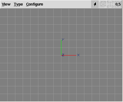
The view window is split into a menu bar and a OpenGL-widget, where interaction and drawing takes place. The title of the view window gives information about name, current type, and the currently active modelling action of the view.
The current modelling action, modelling mode, drawing mode and grid size are also displayed as a set of icons on the right hand side of the view menu bar.
This section discusses the view menu bar.
Note that many menu entries
have keyboard shortcuts that are displayed in each entry.
But those shortcuts only work if the view window
has the keyboard input focus.
The shortcuts are adaptable using the "ayamrc" file
(see section
Ayamrc File).
Another way of navigating the menu is via the "Menu" or
"Alt" key, pressed together with the various underlined characters
in the menu entries.
Here are all entries of the "View" menu:
"Quick Render": the scene is exported to a RIB file using the
camera settings of the current view; then the "QRender" command
(see the preferences) will be called. Note that the RIB export
will not use the RiOption settings for image size but the current
window size instead.
Also note that the environment variable SHADERS will be adapted
to the preference setting Shaders for rendering.
"Render": the scene is exported to a RIB file using the
camera settings of the current view; then the "Render" command
(see the preferences) will be called. Note that the RIB export
will not use the RiOption settings for image size but the current
window size instead.
Also note that the environment variable SHADERS will be adapted
to the preference setting Shaders for rendering.
"Render to File": the scene is exported to a RIB file using the
camera settings of the current view and with a RiDisplay statement that
results in an image file to be produced; then the "FRender" command
(see the preferences) will be called. The image file name will be derived
from the scene file name. Note that the RIB export
will not use the RiOption settings for image size but the current
window size instead.
Also note that the environment variable SHADERS will be adapted
to the preference setting Shaders for rendering.
"Redraw": forces the OpenGL-widget to be drawn, this is
particularly useful if automatic redrawing of the view has been disabled.
"Export RIB" exports the scene to a RIB file. This does exactly the
same as the main menu entry "File/Export/RenderMan RIB", except that
the current view will already be selected in the dialog box.
"Open PPrev", "Close PPrev": those menu entries are just
available, if the compile time option AYENABLEPPREV has been set.
This option is not set for the official Ayam binaries.
Permanent preview (PPrev) continuously writes a RIB stream to
a (fast) RenderMan renderer, a frame for each redraw operation
of the view window that was used to open the preview. This way, the
RenderMan renderer immediately displays all changes in the scene.
This is a great way to test many different camera or light settings without
the need to manually start a rendering process and close the preview window
for each different setting.
As the RIB client library usually is not able to handle multiple open
RIB streams simultaneously, RIB-Export and direct rendering from view
windows are not available until the permanent preview window is closed.
"Create ShadowMap": creates the shadow maps
for the currently selected light source.
See also section
Using ShadowMaps.
"Create All ShadowMaps": creates all shadow maps for the
current scene (regardless of selection).
See also section
Using ShadowMaps.
"Close": the View window will be removed. This entry is not
available for the internal views of Ayam in single window GUI mode."Front"
"Side"
"Top"
"Perspective"
"Trim"
The "Configure" menu may be used to change preferences of the view.
Some preferences are outlined in greater detail in section
ViewAttrib.
"Automatic Redraw", toggles whether the view should
be redrawn, whenever the scene changes. If this is disabled,
a redraw can be enforced using the menu entry "View/Redraw"
or the corresponding keyboard shortcut <Ctrl+d>.
"Drawing Mode" determines whether the view should draw a
wire-frame representation ("Drawing Mode/Draw"), a shaded one
("Drawing Mode/Shade"), a representation
where the wires of the draw mode are drawn over the shaded
representation ("Drawing Mode/ShadeAndDraw"), or
hidden wires and silhouettes ("Drawing Mode/HiddenWire").
See also section
Drawing Modes.
"Modelling Mode" allows to switch the modelling
coordinate system from world space ("Global") to the
space defined by the current parent object ("Local (Level)")
or even the space defined by the currently selected object
("Local (Object)")
See also section
Editing in Local Spaces.
"Draw Selection only", if this is enabled, just the
currently selected objects (and their children) will be drawn.
"Draw Level only", if this is enabled, just the
objects of the current level (and their children) will be drawn.
"Draw Object CS", if this is enabled, small coordinate
systems (three colored lines) will be drawn at the base of each
objects coordinate system.
"AntiAlias Lines", if this is enabled, all lines will
be anti-aliased (smoothed).
"Draw BGImage", if this is enabled, the background
image will be drawn.
"Set BGImage", may be used to set the current background
image of the view, which should be a TIFF file.
This image may also be specified using the view attribute BGImage.
"Draw Grid", if this is enabled the grid will be drawn.
"Use Grid", if this is enabled the grid will be used to
constrain modelling actions to grid coordinates.
"Set Gridsize", may be used to change the size of the grid
associated with this view. Another way to change the grid size is
to use the grid icon menu on the rightmost side, see below.
"Half Size", change width and height to the half of the
current values. This is not available for the internal views in
single window GUI mode.
"Double Size", change width and height to the double of the
current values. This is not available for the internal views in
single window GUI mode.
"From Camera", copy camera settings from the currently
selected camera object to the view.
"To Camera", copy camera settings to the currently
selected camera object from the view.
"Set FOV", lets you specify a field of view value
for the view, and adapts the zoom accordingly. This is just
working for perspective views, of course.
"Zoom to Object", adapt the camera settings, so that
the currently selected objects are centered in the view.
In addition, clipping planes and light position may be adapted for
very small or very large objects.
"Zoom to All", adapt the camera settings, so that
all objects are centered in the view, regardless of current
level and selected objects.
"Align to Object", align the view to the coordinate
system of the currently selected object or to the parent
object of the current level if no object is currently selected.
Apart from the text based menus documented above, there are also some icon based menus in the view window menu bar:
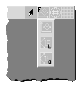
The "Modelling mode" icon menu may be used to quickly change the current
modelling mode (global or local, see also section
Editing in Local Spaces). Apart from a
different icon, the local modes will display a L or O in the lower
right corner of the icon.
The icon, additionally, conveys whether objects or points will currently
modified by a modelling action (for points, a red dot will be present
in the upper right corner of the icon).
Furthermore, the type of the view will be displayed in the upper left
corner of the icon as letter F, S, T, or P for front, side, top, or
perspective views, respectively. Views of type trim get no designating
letter in the icon.
See also the image below:
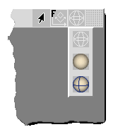
The "Drawing mode" icon menu may be used to quickly change the current
drawing mode, drawing, shading, drawing and shading, or hidden wires.
See also the image below:
See section Drawing Modes for a discussion of the different drawing modes.
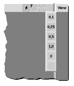
The "Grid" icon menu may be used to quickly change the current grid
size:
On the right hand side in the view menu bar there is a little icon
that displays the current grid size. You may click on the icon to
display a menu with predefined grid size values.
Choosing one of the values 0.1, 0.25, 0.5, or 1.0 will set the
grid size of the view to the chosen value and will additionally
enable drawing of the grid and snapping to the grid.
The entry "X" allows to set a custom grid value.
The last entry will set the grid size to 0.0 and disable drawing of
and snapping to the grid.
If a grid size other than 0.1, 0.25, 0.5, or 1.0 is in effect for the view,
a generic icon (with a X instead of a number) will be displayed in the
icon menu.
See also the image below:
Important keyboard commands of a view window (aside from the view menu shortcuts) are discussed in this section.
Note that the view keyboard shortcuts only work if the view window has the keyboard input focus.
These shortcuts can be adapted using the "ayamrc" file
(see section
Ayamrc File).
Keyboard shortcuts directly modifying the camera, that is associated with the view window, are:
<Left>, <Up>, <Right>,
<Down> rotate viewer around the current camera aim point.
<Shift+Left>, <Shift+Up>, <Shift+Right>,
<Shift+Down> pan the view.
<+>, <->, or <Add>, <Sub>
(on the numeric keypad) zoom the view.
<Ctrl+5> (on the numeric keypad!) resets the views
camera (From and To) to the view type dependent default values.
<.> pans the view to the mark.See section Revert Cursor Key Behavior for a script that swaps the rotate and pan cursor key bindings in parallel views.
Interactive actions modifying the camera, that is associated with the view window, are:
<v> you may move the view with your mouse.
<V> you move the camera in the direction it is
looking. Note that this affects both, from and to setting of the
virtual camera. Furthermore, this movement will have no visible effect in
parallel views.
<R> (note the case!) starts rotating the virtual
camera around the point it is looking to.
<Alt>-key while dragging
the mouse.
<Z> starts zooming the view. Dragging the mouse up
zooms in and dragging the mouse down zooms out.
<Shift>-key.[*]
| Name | Shortcut | Icon |
| Pan View | <v> |
|
| Zoom View | <Z> |
|
| Rotate View | <R> |
|
You may also pan/move the view by dragging with the rightmost mouse button and zoom the view with the middle mouse button without affecting any other active view or modelling action.
If you have a wheel mouse and it is configured to send Mouse4 and Mouse5 button events, Ayam will zoom the view when you turn the wheel.
<PgUp> and <PgDown> allow to cycle through the view
types.[*]
<Ctrl+PgUp> and <Ctrl+PgDown>
cycle through the drawing modes.[*]
<Insert> and <Delete> cycle through the grid
sizes.
<Shift-Insert> and <Shift-Delete> modify the current
grid size.[*]
Using the menu entry "Zoom to Object" or the corresponding
shortcut <Ctrl+o> (<O> for internal views)
the views camera settings can be changed so that the selected
objects will be displayed centered in the view window. This is handy
to search for objects or if the user is simply lost in space.
Closely related to the latter is the "Zoom to All" action,
bound to the <BackSpace> key. This action adjusts
the camera settings so that all objects in the scene will be
visible, regardless of current level and object selection.
Note that both, zoom to object and zoom to all, adjust the clipping planes to the extents of the affected objects and also adapt the position of the light source used for shading.[*] This facilitates working with very large and very tiny objects.
Using the menu entry "Align to Object" or the shortcut
<Ctrl+a> (<L> for internal views)
the views camera settings can be changed so that the view is aligned
to the coordinate system of the currently selected object.
This is handy for modelling in local coordinate systems
(e.g. when editing the control points of some planar curve defined in the
XY-plane that has been rotated around the Y-axis).
See also section
Editing in Local Spaces.
It is also possible to move through the scene hierarchy and change the selection directly in view windows:[*]
<Ctrl+4>, <Ctrl+6> (on the numeric keypad!)
move up and down in the hierarchy respectively, also selecting the parent
or first child.
<Ctrl+2>, <Ctrl+8> (on the numeric keypad!)
select the next or previous object.
<Ctrl+Shift+2>, <Ctrl+Shift+8>
(on the numeric keypad!)
extend the current selection to include the next or previous object.This section explains the draw modes available in Ayam.
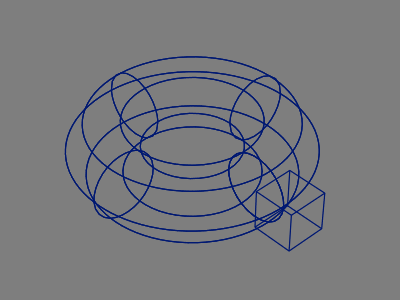
The draw mode "Draw" shows a simple wire-frame representation
of the scene, see the following image:
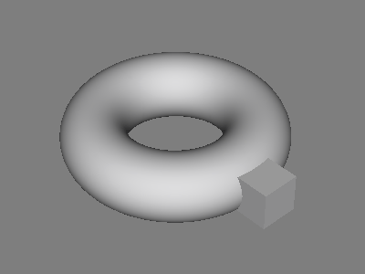
"Draw"The draw mode "Shade" displays the scene as shaded surface
lit by a single headlight, see also the following image:
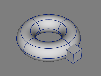
"Shade"The draw mode "ShadeAndDraw" combines the images of the modes
"Shade" and "Draw", see also the following image:
"ShadeAndDraw"The drawing mode "HiddenWire" works like the shade and draw mode,
where the surface shading part is only used to remove hidden bits.
In addition, silhouette edges are detected and drawn.
For best results, use it with anti-aliasing.
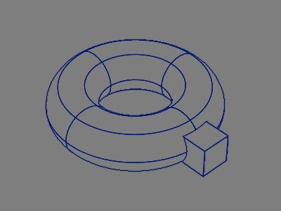
The silhouette detection is shading the scene a second time in a special multi-colored lighting setup. Then, edges are detected in the Z-buffer and color buffer data. If anti-aliasing is not enabled, the resulting edge map is processed by morphological thinning and removal of pixels in the direct vicinity of pixels already drawn, to get one pixel wide lines. Finally, the edge map is used as a largely transparent texture (except for the edges) on a full-screen quad, which is drawn as last object. In case of anti-aliasing, the quad will be drawn four times. See also the image below.
"HiddenWire"The silhouette detection is a slow process and therefore only performed when no interactive action is in progress. The following image shows what will be drawn during interactive actions, compare it also to the complete image above.
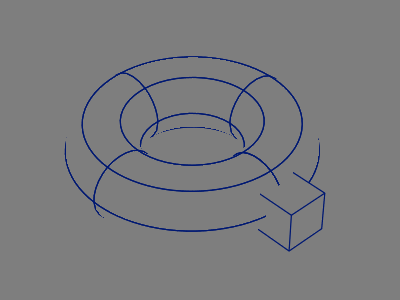
"HiddenWire" without Silhouettes

The toolbox window displays some buttons that start interactive
modelling actions, modelling tools, or create objects.
The toolbox can be opened and closed using the main menu entry
"Special/Toggle Toolbox" unless Ayam is in single window
GUI mode.
Note that in contrast to the keyboard shortcuts of the view windows, the buttons in the toolbox may switch to the modelling actions for all open views. This is the case if Ayam is in single window GUI mode and AutoFocus is enabled or if Ayam is in multi window GUI mode. For more information about the actions see section Modelling Actions.
When creating objects, holding down
the <Ctrl> key while pressing the corresponding toolbox
button will keep the objects selected.
This is especially useful for objects that would move the currently
selected objects to themselves as children (Level, Revolve, Skin etc.).
Several other tool buttons also change their behaviour with modifier keys, check the tooltips.
The toolbox window may be configured by the user using the
hidden preference setting "toolBoxList" in the ayamrc file.
Using this setting you may select from certain groups of buttons
and change the order in which they appear in the toolbox window.
See section
Hidden Preference Settings for
more information.
The toolbox is also open for extension by scripts, see section Script Examples (Toolbox Buttons) for examples.
You may also resize the window to change from the vertical standard
layout to a horizontal one, optimizing the use of precious screen
space. After resizing, the toolbox will re-layout the buttons,
warning you if the space is too small for all buttons to display.
If the window is too big for the desired layout and the hidden
preference setting "ToolBoxShrink" is switched on, the
toolbox will shrink wrap the window to match the space occupied by
the buttons.
Furthermore, using the hidden preference setting "ToolBoxTrans"
the toolbox window can be made transient.
It will then (depending on the window manager or its configuration)
get a different or no decoration, no icon, and will always be iconified
when the main window gets iconified.
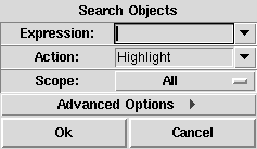
The object search facility allows to find objects in the scene hierarchy according to many different, even script defined criteria and highlight them in the tree view or execute arbitrary actions on them.[*] Object search is controlled by a dialog, see also the image above.
Note, that the object search dialog is not closed immediately after a search operation, this allows multiple search operations with possibly refined parameters.
The first two options "Expression" and "Action" let the
user specify which objects to find and what to do with them, they
are explained in depth in the respective sections below.
Using the parameter "Scope" the search may be limited to certain
sets of objects. By default, when scope is "All", all objects in the
scene are processed, even if the current level is not the root level
and no objects are selected.
If the scope is "Selection" just the selected objects and their
children will be searched.
If the scope is "Level" all objects of
the current level regardless of selection but again including all children
will be searched.
If the scope is "Collection" just the objects found by the previous
search are searched.
Note that the clipboard is never searched.
More options are made available, when the "Advanced Options"
button is pressed.
The option "HighlightColor" defines the color to be used by the
"Highlight" action.
If the options "ClearHighlight" or "ClearClipboard" are switched
on, the highlights and the object clipboard are cleared before a search
starts respectively.
Finally, "InvertMatch" reverts the search logic: if enabled, the
search finds all objects for whose the search expression delivers a
negative results.
When just a simple string is used as search expression, this string
is matched against the types, names, and materials of the objects
to be searched in a case insensitive manner.[*]
The matching allows usage of "*" (matches any sequence of characters),
"?" (matches a single character), and character ranges specified
like this "[A-z]". To match any of *?[] precede them with a
backslash.
If the search expression starts with a "$", "(", or "[" it is
considered a special expression.
The following special search expressions are defined:
find objects of a certain type, for example
$type == "Sphere"
find objects of a certain name, for example
$name == "objname"
objname.
find objects of a certain material, for example
$mat == "matname"
matname.
find objects with a certain property value, for example
$SphereAttr(Radius) == 0.5
find the master of the currently selected instance.
find all instances of the currently selected master, or if the currently selected object is an instance, find all instances with the same master.
find objects for which a procedure or command returns 1, for example
[hasChild]
See section Procedures and Commands for a listing of available commands.
Complex logical expressions may also be created, like e.g.
($type == "Sphere") && ($mat == "wood")
(![hasChild])
Also note that all string based comparisons of e.g. types or names
via "==" are case sensitive.
The default value menu of the "Expression" entry is pre-seeded with
meaningful entries when the search dialog is opened.
What exactly appears in this menu is controlled by the first of the
selected objects.
For instance, if the selected object is a material, the material entry
will contain the material name fetched from this object and will be one
of the first entries, so that searching for objects of this material is
just a matter of two mouse clicks.
If the object is an instance, the first two entries in this menu will
be "Master" and "Instances".
During a search, for every object that matches the given expression the object will be selected and an action will be executed. The following special actions are defined:
All found objects will be colored in the object tree.
Highlighted objects stay highlighted until the tree view is updated
completely (e.g. via the keyboard shortcut <F5>) or partially
(for instance after drag and drop or object clipboard operations).
The node names of the found objects
will be collected in the Tcl list "ObjectSearch(nodes)".
This list can then be used for post-processing by scripts without
the restrictions imposed by the "forAll" command.
The found objects will be added to the clipboard.
The node names of the found objects will be collected, then the list of objects will be processed so that delete is safe, then the objects will be deleted from the scene.
convOb -inplaceaddTag NoExport """forAll" scripting
interface command, certain restrictions apply:See also section Procedures and Commands for a listing of available commands.
The special action "Highlight" also collects the found node names
in the global Tcl list "ObjectSearch(nodes)".
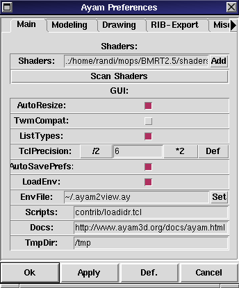
The preferences dialog may be opened using the main menu entry
"Edit/Preferences" or the shortcut <Ctrl+p>.
Use
"Ok" to close the preference editor and
apply all changes,
"Apply" to apply the changes, but leave the editor open,
"Revert" to reset to the settings that have been loaded on
program startup (these are not the factory defaults, to get back to
the factory defaults, restart Ayam with the command line option
"-failsafe" or use the main menu entry
"Special/Reset Preferences"),
"Cancel" to close the dialog without applying any changes.
All changes done after the last press of "Apply" will be lost.Note that while the preference editor is open, AutoFocus is temporarily
turned off and changes to the "AutoFocus" preference setting will
only be realized after the editor is closed.
The preferences are divided into five sections as follows.
The "Main" section contains the most important application setup
related preference settings.
Note that unused settings will not be shown, e.g. on the
Win32 platform, the "TwmCompat" setting will be
hidden.[*]
"Shaders" contains a number of paths (separated by a colon
":" on Unix and by a semicolon ";" on Win32) where Ayam looks
for compiled shaders (e.g. files with the extension ".slc" that
have been compiled with slc from BMRT). Using the "Add" button,
paths may be added with a directory chooser dialog.
After changes to this setting (also after "Revert"!),
use the "Scan for Shaders!" button below.
Note that the environment variable SHADERS will be adapted to match the contents of this preference setting, so that renderers started by Ayam see exactly the same set of shaders as Ayam. However, this does of course not affect any renderers that are started outside the Ayam context, i.e. when rendering exported RIB files from a shell.
Since Ayam 1.22, the shader paths support globbing, i.e. it is possible to specify
"/usr/share/aqsis/shaders/*/"
"/usr/share/aqsis/shaders/surface/"
"/usr/share/aqsis/shaders/displacement/"
"/usr/share/aqsis/shaders/volume/"
"/usr/share/aqsis/shaders/light/"
"Scan for Shaders!" initiates a rebuild of the internal
shader database. All shaders in the directories specified by
the "Shaders" preference setting will be scanned and entered in
that database.
Watch the console for error messages that may appear while scanning.
See also sections
Shader Parsing and
Shader Parsing Plugins for more
information on scanning shaders.The next sub-section contains GUI (user interface) related settings.
"Locale", sets a language for the balloon help texts,
the default value menu shows all currently available locales.
The value will have no effect until Ayam is restarted!
"SingleWindow" toggles, whether Ayam should create just
one main window with internal views and toolbox or use the old
floating windows style GUI. The new single window GUI mode is enabled
by default.
"AutoResize" toggles, whether the main window
should be resized horizontally according to the property GUI whenever
a new GUI is displayed.
This option is not available in the single window GUI mode.
"AutoFocus" controls whether Ayam should automatically
move the focus to a view or the main window, when the mouse pointer
enters it. However, depending on the operating system, window manager,
or their settings, this may only work correctly, when a window
of Ayam already has the focus. On some operating systems or window
managers AutoFocus might not work at all. Furthermore, note that moving
the focus to a toplevel window might also raise it.
In single window GUI mode, AutoFocus additionally manages the input focus of the internal views, tree view, property GUI, and console.
While the preference editor is open, AutoFocus is temporarily
turned off and changes to the "AutoFocus" preference setting will
only be realized after the preferences editor is closed.
"TwmCompat" changes, how Ayam tells the window manager
new geometries of windows. This option has to be toggled if Ayam
fails to correctly remember the geometry of the main window between
two invocations or if the main window jumps downward when properties
are selected.
This option is not available on the Win32 platform and on MacOSX Aqua.
"AutoSavePrefs", if this is switched on, Ayam will write
the preferences settings to the ayamrc file when the program quits.
"BakOnReplace", if this is switched on, Ayam will make
a backup copy of each scene file loaded via the main menu entry
"File/Open" or via the most recently used list.
The backup file will be placed right next to the loaded file
and get an additional file name extension according to the hidden
preference setting "BackupExt".
"AddExtensions", this option may be used to let Ayam
automatically add file name extensions to saved files (if they
do not have already a proper extension).
"EnvFile" specifies the working environment scene file.
This file typically contains some view objects to create a standard
2-, 3-, or 4-view working environment and is automatically loaded
upon each start of Ayam (unless the hidden
preference option "LoadEnv" is switched off) and upon each clearing
of the scene using "File/New" (unless the hidden preference option
"NewLoadsEnv" is switched off).
See also section
Hidden Preference Settings.
"Scripts" is a list of Tcl script files that will
be executed on startup. The scripts do not
have to be specified with full path and
filename.[*]
Furthermore, the scripts and plugins directories (as specified using the
"Plugins" option below) are automatically searched, and the ".tcl"
file name extension is automatically added, so that a setting
of "colfocus;loadayslx"
would load the "colfocus.tcl" script from the scripts directory and the
ayslx shader parsing plugin (via the "loadayslx.tcl" script) from the
plugins directory.":") on Unix and by
a semicolon (";") on Win32."Add" button.
See section Helper Scripts for documentation on the scripts distributed with Ayam.
"Plugins" is a list of directories that contain custom
objects or plugins. Those directories will e.g. be searched for
custom objects when unknown object types are encountered while reading
Ayam scene files. If a matching custom object is found, it will be
automatically loaded into Ayam, so that scene loading may proceed without
an error. If non-absolute paths are used they are considered to be relative
to the directory where the Ayam executable resides.
.../ayam/bin/Ayam.exe
.../ayam/bin/plugins/
.../ayam/bin/plugins/ayslx.dll
":") on Unix and
by a semicolon (";") on Win32."Add" button.
See section Plugins Overview for more information regarding Ayam plugins.
"Docs" is an URL that points to the documentation in
HTML format.
"TmpDir" is the directory, where temporary RIB files are
created, e.g. when rendering directly from view windows.The preference settings "ListTypes", "MarkHidden",
"LoadEnv", and "NewLoadsEnv" are hidden preference
settings since Ayam 1.14, see section
Hidden Preference Settings.
The next section of the preferences, "Modelling",
contains modelling related settings:
"PickEpsilon" is used by the single point editing actions
(see section
Editing Points)
to determine which point of an object has been selected.
A smaller "PickEpsilon" means more exact picking.
The value of "PickEpsilon" should be positive and is expressed
in terms of object coordinates, however, also the view zoom factor modifies
the effective "PickEpsilon" value in a way that for zoomed-in views
a smaller value will be used (and vice versa).
In older versions of Ayam (prior to 1.8), a value of 0.0 was allowed and default. This is no longer the case, the new default value is 0.05.
"LazyNotify" determines whether notification shall
occur on all mouse movements or just on release of the mouse button,
for the interactive modelling actions.
This option may also be toggled easily using the keyboard shortcut
<F6>.
Notification is the mechanism used to inform objects that rely on certain child objects (e.g. the Revolve tool object) about changes of their child objects, so that the parent can adapt to the child objects automagically (see also section The Modelling Concept Tool-Objects).
"CompleteNotify" determines when notification of all objects
depending on references of changed objects takes place:
"Never", for manual control of complete notification
(manual complete notification can be carried out using the main
menu entry "Tools/Force Notification" or using the
keyboard shortcut <F5>);"Always", a complete notification is done whenever the
normal notification is carried out;"Lazy", the complete notification runs
only after a modelling action finished (when the mouse button is
released)."EditSnaps" determines, whether points
should be snapped to the grid when a grid is defined and
in use for the single point modelling actions.
"Snap3D" controls whether points that are snapped to
grid coordinates (in single point editing actions and when grids are active)
should be influenced in all three dimensions, or just the two dimensions
determined by the type of the view.
"FlashPoints" controls flashing of editable points in
the single point modelling actions when they would be modified by
a click and drag action.
Note that a change of this preference option only takes effect for
the next invocation of the single point editing modelling action.
Also note, that there is a similar, albeit hidden, preference option
that controls the flashing of picked objects ("FlashObjects"),
See also section
Hidden Preference Settings.
"RationalPoints" determines the display style of rational points.[*]
In the euclidean style the weights are not multiplied in, whereas in the homogeneous style the weights are multiplied in prior to display. This preference setting also influences the control hull display of NURBS curves and surfaces and some modelling actions like setting the mark from points. See also the following image, showing two standard nine point NURBS circles, where every second control point has a weight value of 0.75, with their control hulls in euclidean and homogeneous style.
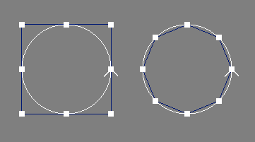
"GlobalMark" toggles whether each view should manage its
own mark (off), or whether there should be just one global
mark (on, default[*]).
Note that enabling this preference setting will not
immediately lead to a global mark set in all windows, one rather
needs to set a new mark that will then become global.
"CreateAtMark" controls whether or not new objects
are to be created at the current mark position
(default: yes).[*]
"DefaultAction" determines the modelling action
that will be active after a press of the <Esc> key
in a view window.
"PickCycle" exchanges the object pick candidates dialog with
a cycling mechanism:[*] when multiple
candidates are available, the first
click selects the first object in the list and each further click on the
same position selects the next object in the list of candidates.
See also section
Selecting Objects by Picking
for more information about picking objects.
"UndoLevels" determines the number of modelling steps
that should be saved in the undo buffer.
If "UndoLevels" is set to 0, the undo system will be disabled
completely.[*]
For more information, see also the section The Undo System.
The preferences in the "Drawing" section let you specify
how objects are being drawn:
"Tolerance" is in fact GLU sampling tolerance, used to
control the quality of the sampling when rendering a NURBS curve
or NURBS patch using GLU.
Smaller tolerance settings lead to higher quality. Useful values
range from 1 to 100.
This setting has no effect for objects that override it
using a local tolerance setting different from 0.
STESS derives a quality/sampling factor from this setting, that leads to comparable sampling quality for a standard viewing distance.
Using the keyboard shortcuts <F2> and <F3>
the GLU tolerance may also be set easily.
"NPDisplayMode" sets the display mode for NURBS patches.
Either the control hull (or control polygon) is drawn (ControlHull), or
just the outlines of the polygons created by the tesselation
(OutlinePoly), or just the outlines of the patch (OutlinePatch).
The latter are available in GLU and STESS variants.
The GLU variants tesselate the surface according to the current
camera transformation. Zooming into an object increases the sampling rate.
This approach is slow, needs to be done for every view
window separately, but delivers high quality where needed.
In addition, surfaces
outside the current viewing volume are culled. Due to the dynamic sampling,
the NURBS parameterization can not be judged easily.
STESS, on the other hand, is tesselating in a uniform way and therefore
the NURBS parameterization can be inferred easily. The tesselation is
done only once, even if there are multiple views, and then cached.
Consequently, the startup cost and memory requirements
of STESS are higher than those of GLU, but repeated drawing is much faster,
even though culling in STESS is currently done on the basis of tesselated
triangles, not entire surfaces.
Another aspect to consider is that GLU operates on the floating point
data type "float" and imposes a serious constraint on knot values:
knots that differ in less than 10E-4 are considered equal.
In contrast, STESS operates on the floating point data type "double"
and uses a more relaxed epsilon of 10E-6.[*]
Finally, the application of instancing does not speed up drawing with GLU,
but lowers the tesselation and memory costs of STESS, as instances use
the cached tesselation of the respective master objects.
Note that the "NPDisplayMode" setting also influences display of
shaded NURBS:
ControlHull shades the control polygon[*],
OutlinePoly (GLU) and
OutlinePatch (GLU) use GLU, and OutlinePatch (STESS) shades the STESS
tesselation. The shaded STESS tesselation of non-planar trimmed NURBS
surfaces is of low quality.
Note also, that the "NPDisplayMode" setting has no effect for
objects that override it locally using a "DisplayMode" attribute
different from "Global".
Toggling between drawing of hulls and outlines may also be
done easily using the keyboard shortcut <F4>.
"NCDisplayMode" sets the display mode for NURBS curves;
just like for surfaces the control hull (control polygon) or the curve or a
combination of both may be displayed.
See also the discussion of GLU vs. STESS above.
Note that this setting has no effect for objects that override it
locally using a "DisplayMode" attribute different from "Global".
Toggling between drawing of hulls and curves may also be
done easily using the keyboard shortcut <F4>.
"ToleranceA" is the GLU sampling tolerance that is
used for display of NURBS curves or patches in all interactive
actions, i.e. while interactively moving objects or editing
control points.
Negative values are interpreted as multiplicand in the following
way. A value of -2 means: use the value from the "Tolerance" setting
multiplied by 2, e.g. if the "Tolerance" is set to 40, a value of 80 will
be used in actions.[*]
The default value 0.0 means no change from the "Tolerance" setting.
In contrast to the "Tolerance" setting above, objects can
not override this setting locally.
"NPDisplayModeA" controls the display mode of NURBS
patches for all interactive actions.
The first and default value ("NPDisplayMode") means: no change.
In contrast to the "NPDisplayMode" setting above, objects can
not override this setting locally.
"NCDisplayModeA" controls the display mode of NURBS
curves for all interactive actions.
The first and default value ("NCDisplayMode") means: no change.
In contrast to the "NCDisplayMode" setting above, objects can
not override this setting locally.
"UseMatColor" determines, whether the shaded representation
uses the color defined by the material of an object for
rendering. If disabled, the color defined by the "Shade" option
(below) will be used instead.
"Background", "Object", "Selection", "Grid",
"Tag", "Shade", and "Light" set the colors that
will be used when drawing or shading the respective primitives.The "RIB-Export" section of the preferences contains settings that
affect how RIBs are created.
"RIBFile" allows to set the file Ayam is exporting
RenderMan Interface Bytestreams (RIBs) to. Note that some
file names have special meaning:
If "RIBFile" is set to "Scene" (this is the default)
the RIB file name will be derived from the name of
the currently loaded scene with the last extension replaced by
".rib". If "RIBFile" is set to "Scenefile", the leading
path will be stripped from the scene name additionally.
Use "Scenefile", for rendering with shadow maps.
This way the scene will use relative paths to load the shadow maps and
the RIBs may be moved around more easily.
"Ask" is another special setting, that allows
to select a different file name each time the scene is exported.
A file selection dialog will pop up, after the selection of the
view to export.
The same effect may be achieved by leaving "RIBFile" totally
empty.
If "RIBFile" is set to "rendrib",
libribout.a does not create a RIB file at all, but immediately pipes the
resulting byte stream into rendrib (the BMRT renderer) for rendering.
The same goes for "rgl".
Moreover, file names that start with a pipe symbol "|" will
cause the program after the pipe symbol to be started by libribout
and the written RIB to be piped into. This works e.g. with
Photorealistic RenderMan, try it out with "|render".
In the latter cases of direct rendering, you will probably want to set
up the RIB to render to the display (read leave the "Image"
preference setting empty.
However, when you use these options of direct rendering, be warned, that
for the time of the rendering Ayam will be frozen (it will neither
respond to mouse clicks nor will it update any windows), until the
rendering is finished and the display window of the renderer is closed.
"Image" specifies the image file that will be created,
when the exported RIB file is rendered.
When this option is set to "RIB", rendering will create image
files that are named as the exported RIB file (with the last
file extension replaced by ".tif"). Again, setting
it to "Ask" will cause a dialog box to appear,
each time the scene is exported to RIB.
Note that in contrast to the "RIBFile" option, leaving the field
totally empty is not equal to entering "Ask" but generates
RIB files that will be set up to render to the display.
"ResInstances", if this is enabled all instance
objects are resolved (temporarily) before being written to the RIB file.
"CheckLights", if this is enabled Ayam will
check the current scene for lights before RIB export. If no lights or
no lights that are actually switched on are to be found in
the scene, a distant headlight will be added to the scene
automatically for RIB export.
"DefaultMat" determines a default material setting
that should be written in the top level of the RIB, so that it
is in effect for all objects, that are not connected to a material
object. Many RenderMan compliant renderers will not render the
objects at all, if no material is defined.
The default "matte", writes just a simple
RiSurface "matte" (without parameters) to the RIB.
The setting "default" looks for a material object named
"default" and writes it's complete shaders and attributes,
if it does not find such a material it falls back to "matte".
The setting "none" does not write any default material setting.
"RIStandard" determines whether Ayam
should omit all non standard RenderMan interface options and
attributes on RIB export.
"WriteIdent" determines, whether Ayam should
write special RiAttributes
(RiAttribute "identifier" ["name"])
with the names of the objects to the RIB to aid in RIB file debugging.
"ShadowMaps" determines, whether shadow maps should
be used, when writing light sources. It is not sufficient
to switch this on to render using shadow maps, light sources
that shall use shadow maps have to be parameterised
as well, see section
Using ShadowMaps.
If "ShadowMaps" is set to "Automatic", the
exported RIBs will automatically render and use all shadow maps;
if it is set to "Manual", the shadow maps will be rendered on
user request only (e.g. using the view menu entry:
"View/Create All ShadowMaps"). "Manual" should be used,
when rendering directly from view windows with shadow maps.
"ExcludeHidden" causes hidden objects not to be
exported to RIB files.
"RenderMode" allows to switch between two different methods
of forcing a renderer to render to the screen (via a RiDisplay statement
in the exported RIB, necessary for e.g. PRMan and RDC;
or via a command line argument, e.g. -d for rendrib from BMRT).
"AutoCloseUI" controls whether the Rendering GUI dialog
window should be closed automatically when the renderer signals
that the rendering finished.
"QRender" determines the command that should be executed
upon quick rendering a view, %s denotes the name of the RIB file.
"QRenderUI", enables the Rendering GUI for quick rendering,
see discussion of "RenderUI" below.
"QRenderPT", progress template for quick rendering,
see discussion of "RenderPT" below.
"Render" determines the command that should be executed
upon normal rendering of a view, %s denotes the name of the RIB file.
"RenderUI" enables the renderer user interface (Rendering GUI),
which consists of a simple progress bar, a label that displays the
estimated or elapsed rendering time, a checkbutton to control
ringing the bell when the rendering is finished,
and a cancel button. This GUI is displayed
when a renderer is invoked directly from a view window
using the "Render" view menu entry (or the equivalent keyboard shortcut).
Proper work of this GUI depends on the existence of
two external programs: "cat" and "kill" (those programs
should be available on every Unix platform). If you do not have
those programs in your path, do not enable the RenderUI option.
On the Win32 platform you may also use an internal kill command
"w32kill" that has been introduced in Ayam 1.4.
See also section
Hidden Preference Settings.
"RenderPT" is a string that contains a progress output
template used by Ayam to determine the current percentage of completion
of the rendering for display in the Rendering GUI. The special symbol "%d"
denotes the position of the percentage number in the output of the renderer.
For rendrib from BMRT 2.6 this should be set to "R90000 %d" and
the special command line option "-Progress" should be used for
the renderer command (see "Render" above).
For rendrib from BMRT 2.5 it should be set to "Done computing %d"
and no special option has to be given to the renderer."percent".
The output to parse will be inserted
in the regexp command template in place of "string".
The dummy output variable is needed, because Tcl regexp always outputs the
complete matching line into the first variable.
fish.rib (222): - 10.00 percent
regexp -- {^.* - (\[0-9\]+)} string dummy percent
Elapsed: 10.1440s Done: 64% |******************** |
$ at the end):
regexp -- {(\[0-9\]+)%(\[ |*\]+)$} string dummy percent
"FRender", renderer command to use for direct rendering to image
files (via view menu entry "Render to File").
"FRenderUI", enables the Rendering GUI for the direct rendering
to image files, see discussion of "RenderUI" above.
"FRenderPT", progress template for the direct rendering to
image files, see discussion of "RenderPT" above.
"SMRender", renderer command to use for the rendering of shadow maps
(e.g. view menu entry "View/Create All ShadowMaps"),
see also section
Using ShadowMaps.
%s denotes the name of the RIB file.
"SMRenderUI", enables the Rendering GUI for the rendering
of shadow maps, see discussion of "RenderUI" above.
"SMRenderPT", progress template for the rendering
of shadow maps, see discussion of "RenderPT" above.
"SMFileFormat", designates the file format of the shadow maps,
use "zfile" for RenderMan and "shadow" for Gelato.
"SMFileType", type of shadow maps to be created, currently
available types are "z" – normal shadow maps (for RenderMan
renderers and Gelato), "avgz" – Woo shadow maps (for Gelato only!),
and "volz" – volume shadow maps (for Gelato only!).
"SMChangeShaders", toggles, whether Ayam should automatically
prepend a "shader" to light shader names for lights that use shadow maps
upon RIB export. Not changing the shader names is necessary for Gelato.
"PPRender" is the name of the renderer to use for the
permanent preview feature (see also section
View Menu).
This setting is just available, if the compile
time option AYENABLEPPREV has been set.
This option is not set for the official Ayam binaries.Note that many renderer related preferences can be set at once using the
select renderer tool via the main menu "Special/Select Renderer"
(see also section
Special Menu). In fact,
using "Special/Select Renderer" first, then fine tuning the
renderer setup using the preferences editor is the suggested way to
switch Ayam to a certain RenderMan renderer.
The "Misc" section of the preferences contains the dreaded
miscellaneous settings.
The first sub-section deals with error message handling:
"RedirectTcl" controls whether error messages
stemming from Tcl/Tk should be redirected to the console,
rather than be handled by Tcls sometimes annoying error
handling dialog box. However, this dialog box with the built in
stack trace can also become very handy, while writing and debugging
Tcl scripts.
"Logging" determines, whether error messages should
be written to the file specified by the "LogFile" option.
If this is enabled, you should clear the log manually from time
to time, as Ayam will always append to "LogFile".
"LogFile"; see above.
"ErrorLevel", this option controls how many messages
should be written to the Ayam console. Available
values are:"Silence" no output,"Errors" only error messages,"Warnings" only error and warning messages,
and finally"All" (default) all messages, even informative,
should be written to the console.
The last sub-section contains miscellaneous user interface related preferences:
"SaveAddsMRU"; if this is switched on, saving to a file
will add that file to the most recently used files list in the
main menu for quick access.
"TclPrecision"; this is the precision Tcl handles floating
point number to string conversions with. You may want to decrease this
value to about 5 if any numbers in the entry fields are represented
in an exact, but also too lengthy and hard to read fashion,
like 0.4999999 instead of 0.5. Note that some model precision is lost
in doing so. The default value used by Tcl is 12 and results in no
loss of precision. The default value used by Ayam is 6 and should
result in a good balance between precision and readability.
Related hidden preference options are "NormalizeDigits",
"NormalizePoints", and "NormalizeTrafos", see also
section
Hidden Preference Settings.
"SaveDialogGeom" controls whether the geometry of various dialog
windows should be remembered by Ayam, the settings available are"Never": the dialog windows are
always opened in standard size, centered on the screen;"WhileRunning":
the window geometry will be remembered as long as Ayam is
running;"Always": the window geometry will be stored
in the saved preferences, thus, also surviving a restart of Ayam.
Note that the height of the preferences dialog window will always be adapted
to the currently open preferences section, no matter how "SaveDialogGeom"
is set.
For more geometry saving related information, see also sections SaveMainGeom and SavePaneLayout.
"SMethod"; is the sampling method used by the NURBS tesselation
facility that converts NURBS surfaces to PolyMesh objects.
See also section
Tesselation Tool.
Six sampling methods are available:
"ParametricError"
ensures that the distance between the tesselated surface and the original
surface is no point bigger than the value specified by "SParamU".
"PathLength" ensures that no edge of a
polygon generated by the tesselation is longer than the value specified
by "SParamU" and the tesselation method
"DomainDistance" (the default up to 1.22) simply tesselates
the NURBS surface into equally sized pieces with regard to parametric
space; "SParamU" and "SParamV" control the number of sampling
points in U and V direction respectively per unit length.
This leads to different numbers of samples for knot vectors
of different total length in parameter space.
"NormalizedDomainDistance"
ensures that the tesselation creates the same number of sample
points (as given via "SParamU" and "SParamV") for
knot vectors of any total length in parameter
space[*]
and
"AdaptiveDomainDistance" additionally adds
sample points depending on the number of control points (width or
height of the patch) to provide a better adaptation to complex
patches.[*]
"AdaptiveKnotDistance" normalizes the number of sample
points to the number of knot intervals and the total length of
the knot vector.[*]"AdaptiveKnotDistance" is the default
since Ayam 1.23.
Note that the sampling method controlled by this preference option is not used for NURBS display in Ayam. See also Drawing Preferences.
The tesselation facility is based on the GLU (V1.3+) NURBS tesselator.
"SParamU"; is a parameter for the sampling method above."AdaptiveKnotDistance" is 3.
Higher values lead to better quality and more tesselated polygons."DomainDistance" is 8. Higher
values lead to better quality and more tesselated polygons."PathLength" is 1.5.
Smaller values lead to better quality and more tesselated polygons."ParametricError" is 0.25.
Smaller values lead to better quality and more tesselated polygons.
Note that "SParamU" is expressed in object space units for the
"PathLength" and "ParametricError" sampling methods.
"SParamV"; is just available for the sampling methods
"DomainDistance", "NormalizedDomainDistance",
"AdaptiveDomainDistance", and"AdaptiveKnotDistance"."SParamU"
parameter above.See also the next two images and corresponding tables that allow to compare the results of four main sampling methods with different parameters.
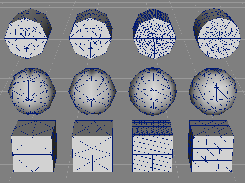
| Method | ParametricError | PathLength | DomainDistance | AdaptiveKnotDistance |
| Parameter | 0.25 | 1.5 | 8 / 8 | 3 / 3 |
| Cylinder | 88 | 104 | 368 | 192 |
| Sphere | 96 | 80 | 112 | 120 |
| Box | 36 | 60 | 384 | 108 |
| Total | 220 | 244 | 864 | 420 |
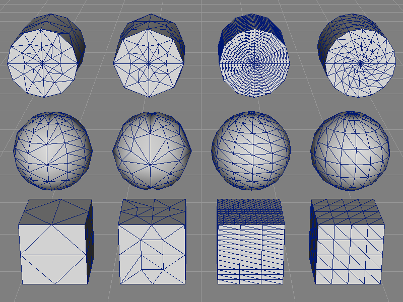
| Method | ParametricError | PathLength | DomainDistance | AdaptiveKnotDistance |
| Parameter | 0.125 | 0.9 | 12 / 12 | 4 / 4 |
| Cylinder | 152 | 168 | 840 | 352 |
| Sphere | 216 | 160 | 264 | 224 |
| Box | 36 | 108 | 864 | 192 |
| Total | 404 | 436 | 1968 | 768 |